Freya Yang
+86 18318948097
+852 62667476
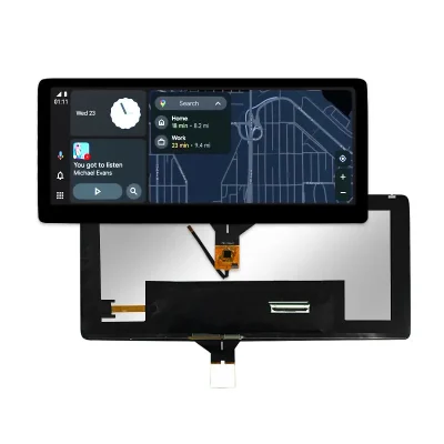
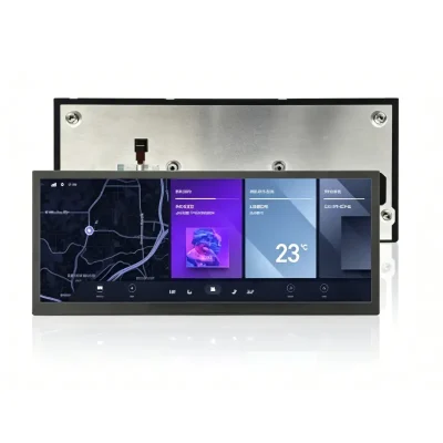
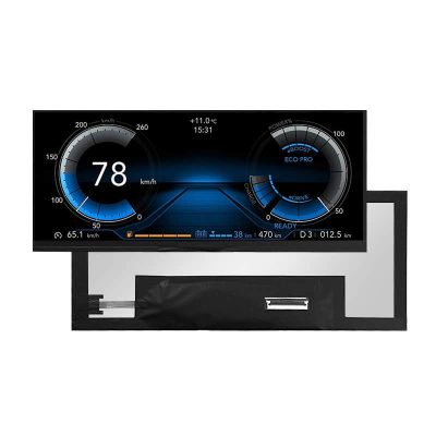
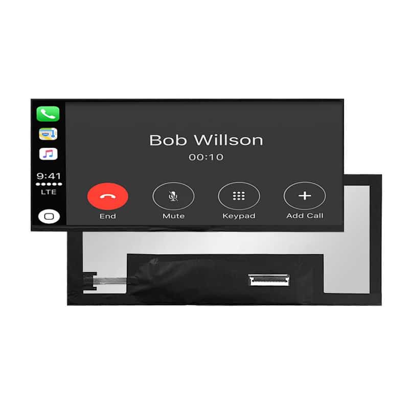
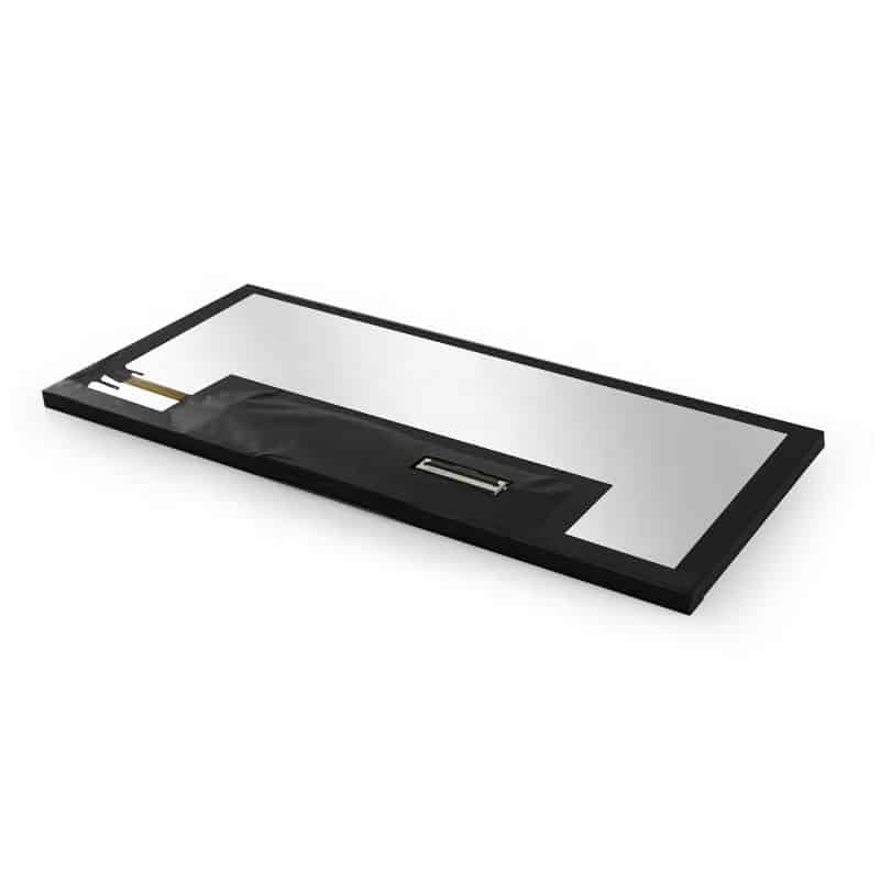
10.25 Inch Wide Cockpit LCD Panel Touch Display for Automotive HMI



Model P/N
Size
Resolution
Brightness
Viewing Angle
Connector Type
Operating Temp
Overall(mm)
huisoar
HS103Z7P-K10-50
Brand
Panel Size (inch)
Model P/N
Resolution
Brightness (nits)
Viewing Angle
Contrast Ratio
Response Time
Overall (mm)
Active Area (mm)
Refresh Rate
Display Colors
Panel Type
Connector Type
Surface Treatment
Operating Temp
Touchscreen Type
Storage Temp
Work Mode
Pixel Format
Control Type
Operating Environment
Designed For
10.25 Inch Wide Cockpit LCD Panel for Automotive HMI
A panoramic 1920 × 720 capacitive-touch panel with 1000-nit luminance and LVDS for wide vehicle-interface layouts.
Product Summary
The 10.25 Inch Wide Cockpit LCD Panel provides an ultra-wide display format for automotive HMI prototypes, cockpit information systems and specialty-vehicle interfaces. Its native 1920 × 720 resolution supports instrument graphics, navigation regions, operating status, alerts and vehicle-control content across a long horizontal canvas.
The panel combines 1000-nit luminance, capacitive touch, LVDS signaling, Normally Black display mode and a 243.648 × 91.368 mm active area. Integration requires a compatible display host, defined touch-controller architecture, confirmed backlight system and an approved production drawing.
Key Specifications
| Specification | Value |
|---|---|
| Display size | 10.25 inch |
| Resolution | 1920 × 720 pixels |
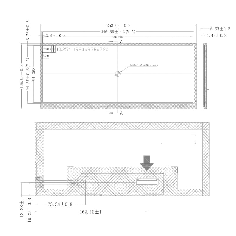
| Active area | 243.648 × 91.368 mm |
| Pixel pitch | 0.1269 × 0.1269 mm |
| Pixel arrangement | RGB vertical stripe |
| Display colors | 16.7 million colors |
| Color gamut | NTSC 70% minimum |
| Luminance | 1000 nits |
| Display mode | Normally Black |
| Display interface | LVDS |
| Touch technology | Capacitive |
| Surface treatment | HC |
| Surface hardness | 3H |
| Logic-power reference | 0.5 W maximum |
| Operating temperature | −30°C to +85°C |
| Storage temperature | −40°C to +95°C |
| Mechanical outline | Approval drawing required because current references conflict |
Panoramic 1920 × 720 Cockpit Layout
Wide-Format Interface Composition
The 1920 × 720 raster creates a panoramic workspace for information that benefits from horizontal separation. A cockpit interface can divide the screen into instrument, navigation, alert, media and system-control zones without relying on a taller conventional aspect ratio.
The native raster should be used whenever practical. Scaling from a mismatched source can soften text, distort circular gauges or change the proportions of interface elements.
Interface planning should define:
- Driver and passenger viewing positions
- Primary and secondary information zones
- Minimum text and icon sizes
- Warning-message placement
- Touch-target dimensions
- Day and night visual themes
- Screen orientation and mounting angle
Active Area and Pixel Geometry
The active image area measures 243.648 × 91.368 mm. This value defines the visible pixel region and should be separated from cover-lens dimensions, bezel opening, touch-active area and complete module outline.
The 0.1269 × 0.1269 mm pixel pitch supports fine text, gauge markings and graphical status elements across the ultra-wide panel.
1000-Nit Optical Design
Finished-System Readability
The panel luminance is specified at 1000 nits. This level provides a strong starting point for vehicle-cabin and other bright-ambient installations, but it does not independently establish finished-system sunlight readability.
A 1000-nit panel does not by itself establish finished-system sunlight readability after cover glass, touch layers, reflections, dimming and thermal conditions are applied.
The optical review should include:
- Cover-lens transmission
- Touch-sensor transmission
- Air gap or optical bonding
- Front-surface reflectance
- Decorative printing
- Panel mounting angle
- Direct and indirect sunlight
- Night-time dimming
- Backlight power
- Enclosure temperature
Brightness should be validated on the completed display stack rather than on the bare panel alone.
Normally Black Mode and Color Coverage
Normally Black mode can support dark cockpit themes and controlled off-state appearance. The panel also supports 16.7 million colors and an NTSC 70% minimum color-gamut reference.
These values provide a basis for instrument graphics, status indicators, maps and branded interface content. They do not establish color-critical calibration, HDR performance or a specific automotive color standard.
The HC surface and 3H hardness provide panel-surface references. They do not prove impact resistance, scratch immunity, chemical resistance or the performance of a finished cover lens.
LVDS and Capacitive-Touch Integration
Display-Host Qualification
The panel uses an LVDS display interface. LVDS identifies the signaling family but does not define the complete electrical implementation.
An LVDS interface name does not guarantee timing, voltage, mapping, connector or pin compatibility.
Before connecting the panel, confirm:
- Native 1920 × 720 timing
- Pixel clock and blanking
- LVDS channel count
- Color-bit depth
- JEIDA or VESA mapping
- Connector manufacturer and pitch
- Pin-1 orientation
- Complete pin assignment
- Panel-logic voltage
- Panel-enable requirements
- Ground and shielding arrangement
- Backlight-enable and dimming controls
The host schematic, panel specification, cable drawing and controller documentation should be reviewed before a sample is powered.
Touch-Controller Definition
The capacitive-touch label confirms the sensing technology but does not identify the controller or host interface.
The capacitive-touch label does not define the touch controller, host interface, firmware or cover-lens construction.
A complete touch specification should identify:
- Touch-controller model
- USB, I²C or other communications interface
- Supply voltage
- Touch-point count
- Interrupt and reset signals
- Firmware environment
- Active touch area
- Cover-lens material and thickness
- Decorative printing
- FPC position and direction
- Bonding method
- Glove, water or noise requirements when applicable
Touch functionality should be approved with the intended host, cable, lens and firmware.
Mechanical Integration of the 10.25 Inch Wide Cockpit LCD Panel
Conflicting Outline References
The current mechanical references do not define one consistent production outline. The tabulated panel dimensions differ from the dimensioned drawing, and the drawing includes several side-depth values that appear to describe different assembly layers.
Mechanical release must therefore use a revision-controlled production drawing that defines:
- Bare panel outline
- Touch assembly outline
- PCBA outline
- Maximum local depth
- Active area
- Viewing area
- Cover-lens outline
- FPC exit and orientation
- Connector position
- Keep-out regions
- Mounting datum and tolerances
A nominal size copied from one reference should not be used to release enclosure tooling.
PCBA, FPC and Cover-Lens Clearance
The complete display assembly may include substantially more depth and height than the bare LCD cell. Enclosure planning should account for:
- Rear PCBA
- Touch FPC
- LCD FPC
- Connector engagement
- Cable bend radius
- Cover glass
- Optical or perimeter bonding
- Gasket
- Support frame
- Backlight-driver components
- Ventilation and thermal path
The 10.25 Inch Wide Cockpit LCD Panel should be checked in the intended housing before mold or bracket release.
Temperature and Qualification Boundaries
The stated operating range is −30°C to +85°C, and the storage range is −40°C to +95°C.
These values support wide-temperature evaluation, but they do not independently prove:
- Automotive qualification
- Continuous operation at maximum temperature
- Thermal-cycle endurance
- Humidity resistance
- Vibration resistance
- EMC or ESD performance
- UV resistance
- Waterproofing
- Backlight lifetime
- Complete-system reliability
Qualification should use the selected panel, touch controller, cover lens, cable, host board, backlight drive and enclosure.
Application and Configuration Review
The panel can be evaluated for:
- Automotive HMI prototypes
- Cockpit information displays
- Center-stack interfaces
- Secondary vehicle-control panels
- Specialty-vehicle displays
- Off-highway equipment interfaces
- Transport-equipment HMIs
- Wide-format embedded systems
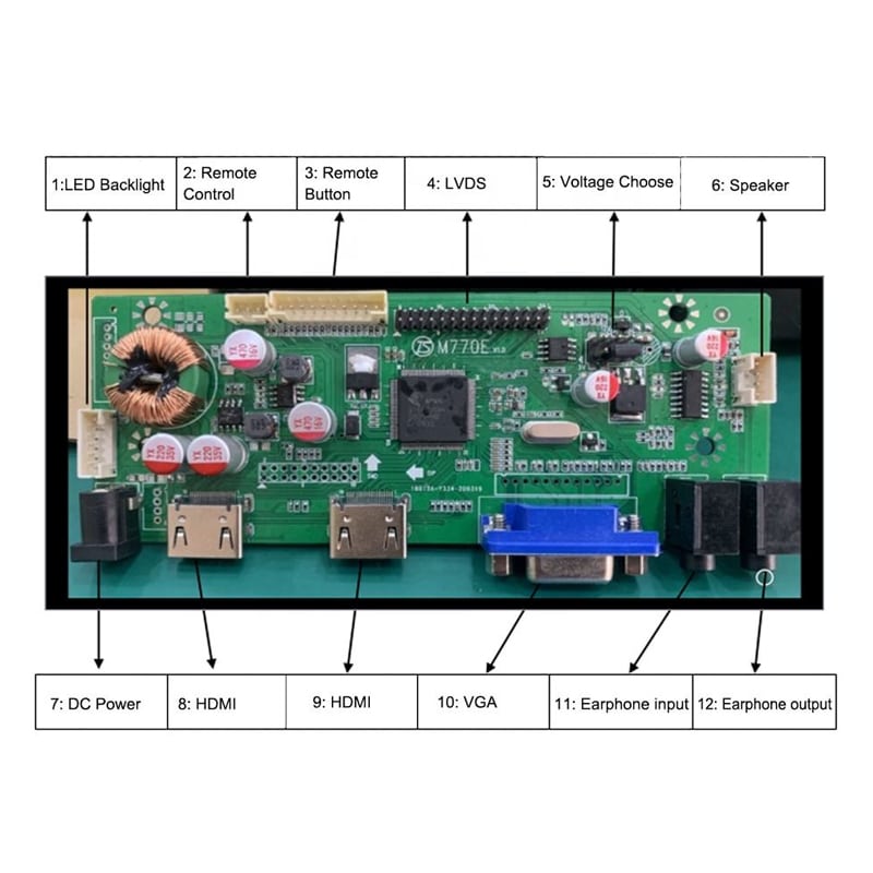
The product is a component display, not a finished infotainment system. HDMI inputs, vehicle communications, audio, operating systems, cameras, media functions and complete power conversion require additional hardware.
Configuration Scope
Project review may cover:
- Touch-controller and interface selection
- Cover-glass design
- Decorative printing
- Optical bonding
- LVDS cable and pin definition
- Backlight drive and dimming
- Mechanical drawing consolidation
- FPC adaptation
- Enclosure integration
- Product labeling
- Qualification documentation
Custom configurations are generally reviewed from 500 pieces, subject to tooling requirements, material availability and the requested specification. Sample and standard-module quantities are confirmed separately.
Procurement Checklist
Submit:
- Host processor or controller-board model
- Native 1920 × 720 timing
- LVDS channel and bit mapping
- JEIDA or VESA assignment
- Complete connector pinout
- Connector manufacturer, pitch and orientation
- Panel-logic voltage
- Backlight input and dimming requirements
- Touch-controller model or target interface
- Touch firmware environment
- Cover-lens drawing
- Optical-bonding requirement
- Required finished-front luminance
- Enclosure and bezel drawings
- Approved mechanical reference
- FPC routing and bend limits
- Operating and storage conditions
- Qualification requirements
- Sample quantity
- Annual demand
FAQ
About 10.25 Inch Wide Cockpit LCD Panel
What must be checked before connecting the panel to an LVDS controller?
How should the 1000-nit performance be evaluated behind cover glass?
What touch information is required before integration?
Which mechanical dimensions should control the enclosure?
How should the wide-temperature range be qualified?
Freya Yang
+86 18318948097