Freya Yang
+86 18318948097
+852 62667476
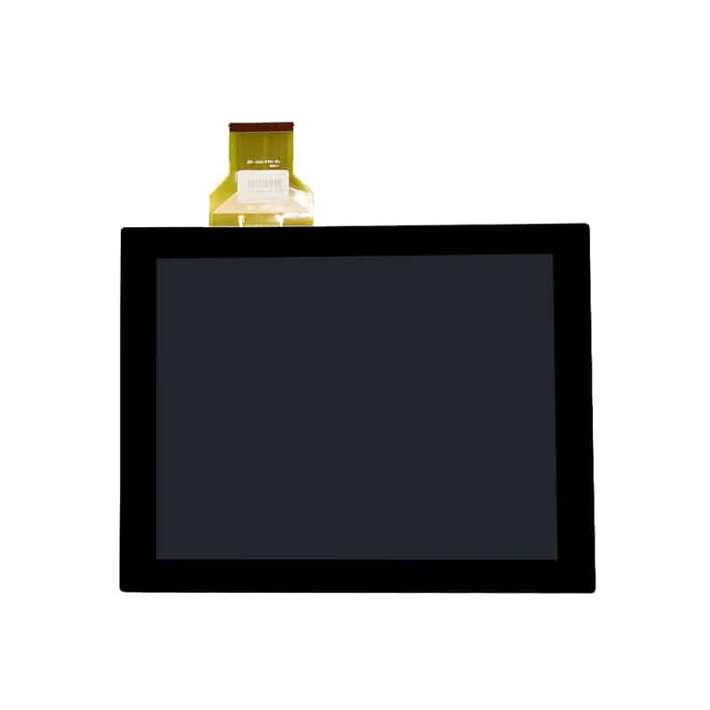
12.1 Inch XGA USB Touchscreen Display Module for Industrial HMI


Model P/N
Size
Resolution
Brightness
Viewing Angle
Connector Type
Operating Temp
Overall(mm)
huisoar
HS0121H500-CPT
Brand
Panel Size (inch)
Model P/N
Resolution
Brightness (nits)
Viewing Angle
Contrast Ratio
Response Time
Overall (mm)
Active Area (mm)
Refresh Rate
Display Colors
Panel Type
Connector Type
Surface Treatment
Operating Temp
Touchscreen Type
Storage Temp
Work Mode
Pixel Format
Touch Interface
Control Type
Protective Glass Specification
Operating Environment
Motherboard Type
Designed For
12.1 Inch XGA USB Touchscreen Display Module for Industrial HMI
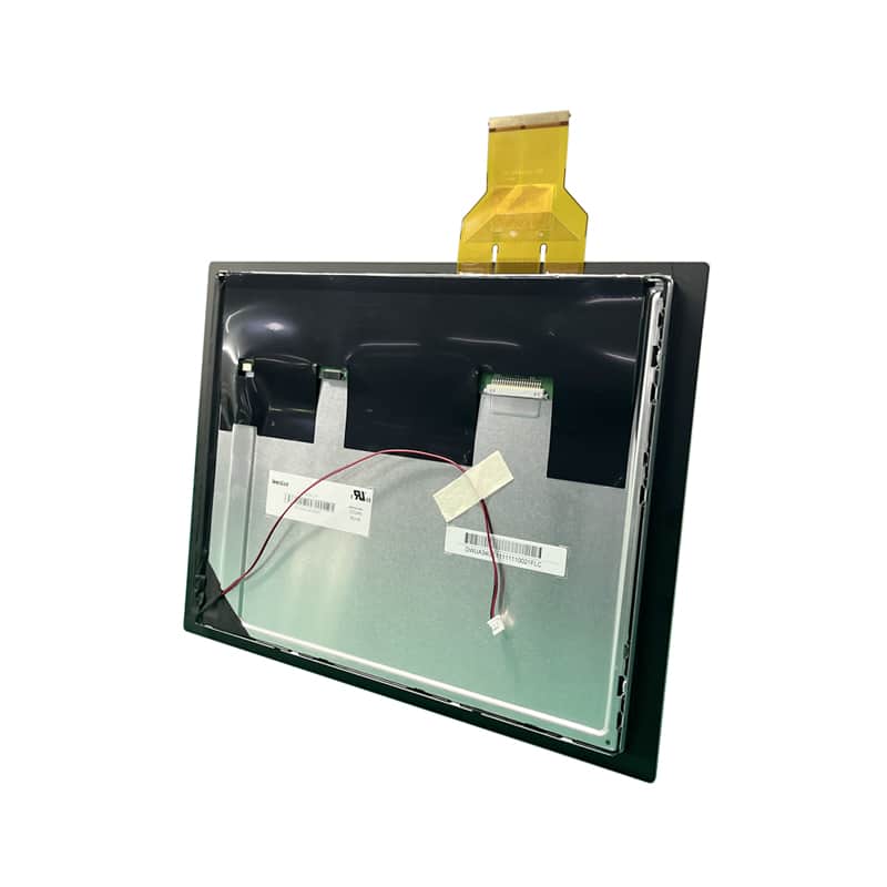
This 12.1-inch IPS assembly combines native 1024 × 768 output, 500 cd/m² luminance, LVDS video input and a separate USB capacitive-touch path for industrial interfaces.
Product Summary
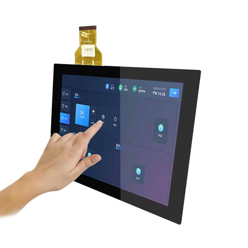
The XGA USB Touchscreen Display Module is intended for industrial HMI projects that require a traditional 4:3 workspace, physical touch interaction and separate video and touch connections.
Its native 1024 × 768 resolution supports XGA operator-interface layouts, equipment menus, alarms, process values and control graphics without converting the application to a widescreen format. The IPS LCD provides a 500 cd/m² luminance grade for indoor equipment and controlled high-ambient-light environments.
The LCD image signal and touch data follow separate paths. LVDS carries the display image, while USB connects the projected capacitive touch controller to the host system. Both paths must be qualified independently before the equipment design is released.
Key Specifications
| Parameter | Value |
|---|---|
| Display size | 12.1 inch |
| Native resolution | 1024 × 768 pixels |
| Resolution class | XGA |
| Aspect ratio | 4:3 |
| Panel technology | IPS TFT LCD |
| Luminance | 500 cd/m² |
| LCD signal interface | LVDS |
| Touch interface | USB |
| Touch technology | Projected capacitive touch |
| Touch construction | G+G CTP + LCD |
| Touch points | 5–10 points by configuration |
| Surface hardness | 6H |
| Touch transmittance | ≥85% |
| Assembly outline | 260.5 × 204.0 × 9.0 mm |
| Operating temperature | −20°C to +70°C |
Planning Native XGA HMI Content
Using the 1024 × 768 Workspace
The 1024 × 768 format provides a 4:3 canvas suited to control applications that use structured data rather than widescreen video.
Typical interface areas can include:
- machine state
- operating mode
- alarm history
- numerical process values
- trend charts
- equipment diagrams
- maintenance instructions
- setup menus
- on-screen controls
- user access prompts
Using the native resolution avoids unnecessary scaling and helps maintain clear text, line graphics and control icons.
Preparing Operator Interface Assets
Before finalizing the software interface, confirm:
- native panel timing
- supported refresh rate
- screen orientation
- color format
- LVDS bit mapping
- startup image behavior
- touch coordinate orientation
- touch calibration
- sleep and wake behavior
- USB reconnect handling
- touch behavior during system startup
- safe spacing between interactive controls
Touch targets should be tested on the actual cover-glass stack rather than judged only from a desktop simulation.
XGA USB Touchscreen Display Module Integration
Qualifying the LVDS Video Path
The LVDS label does not establish compatibility by itself.
Engineering should verify:
- number of LVDS channels
- data width
- connector manufacturer
- connector part number
- complete pin assignment
- pair mapping
- clock polarity
- pixel clock
- horizontal and vertical timing
- panel voltage
- panel-enable sequence
- backlight enable
- dimming method
- cable contact side
- cable length
- shielding and grounding
A controller board that supports 1024 × 768 may still use a different connector, voltage or mapping.
Qualifying the USB Touch Path
The USB connection carries touch-controller data, not the LCD image.
The host must independently support:
- touch-controller enumeration
- required USB class
- approved VID/PID
- operating-system driver
- touch-point count
- coordinate orientation
- calibration method
- suspend and resume
- hot reconnect
- electrical grounding
- cable retention
- EMC behavior
USB touch support on the operating system does not prove that every touch-controller revision will operate identically.
Confirming Touch Configuration and Driver Support
The approved configuration should state whether it uses five or ten touch points. It should also identify the controller-board revision, firmware version and operating-system support.
ILI2511 identification should not be interpreted as proof of universal compatibility or as evidence that the host must perform a particular initialization or register-programming procedure.
Mechanical and Optical Integration
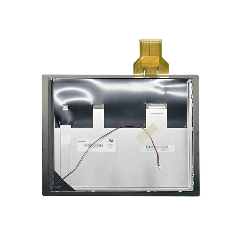
The complete assembly is specified at 260.5 × 204.0 × 9.0 mm.
Before enclosure release, confirm:
- exact visible opening
- LCD active area
- cover-lens outer dimensions
- touch sensor dimensions
- mounting-hole locations
- adhesive border
- cable-exit position
- LCD FPC orientation
- touch-controller-board position
- USB cable routing
- rear-component clearance
- bracket tolerances
- glass-edge protection
- service-removal path
The supplied active-area value requires clarification because it is too close to the overall outline for a 12.1-inch XGA LCD. Use the approved mechanical drawing rather than deriving the bezel opening from that value.
The G+G capacitive structure provides a rigid touch surface. The stated 6H hardness describes the surface grade and should not be presented as an impact rating.
A touch transmittance value of at least 85% describes the touch stack. Finished-display luminance may also be affected by cover glass, optical bonding, surface treatment and viewing conditions.
Suitable Industrial HMI Applications
Automation Control Panels
The XGA layout can support equipment states, operating parameters, trends and interactive control functions in embedded automation panels.
Machine Operator Consoles
A 12.1-inch touch area can provide a practical workspace for machine setup, alarm acknowledgement and process monitoring.
Laboratory and Test Equipment
The panel can be evaluated for test instruments that need graphs, numerical values, menu navigation and direct operator input.
Service and Diagnostic Terminals
The 4:3 interface can support diagnostic menus, maintenance procedures and equipment-status screens.
Embedded Equipment Interfaces
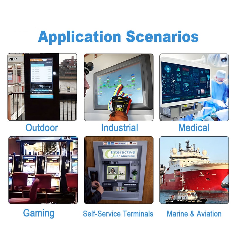
The module can be considered for access-control equipment, production tools, inspection systems and other embedded operator interfaces after signal, touch and environmental qualification.
Application references are integration routes and do not imply product-level certification.
Customization and Engineering Review
Project review can cover:
- cover-glass dimensions
- cover-glass thickness
- black border
- logo or silk printing
- AF, AR or AG surface treatment
- optical bonding
- touch-point configuration
- touch-controller revision
- USB or alternative touch interface
- FPC length and orientation
- LVDS cable matching
- controller-board selection
- mounting structure
- brightness requirements
Custom configurations are generally reviewed from 500 pieces, subject to tooling requirements, material availability and the approved specification. Sample and standard-module quantities are confirmed separately.
Procurement Checklist
Before approving a sample or production design, confirm:
- assigned model and revision
- native 1024 × 768 timing
- LVDS channel count
- LVDS bit width
- pair mapping
- connector part number
- full LCD pinout
- panel supply voltage
- panel current
- backlight voltage
- backlight current
- enable and dimming signals
- cable contact direction
- USB touch-controller model
- touch-controller VID/PID
- firmware revision
- five-point or ten-point configuration
- operating-system driver
- touch calibration
- G+G stack
- 6H surface grade
- ≥85% transmittance grade
- exact LCD active area
- cover-lens visible area
- 260.5 × 204.0 × 9.0 mm outline
- mounting and adhesive details
- FPC and USB cable exit
- operating temperature
- storage temperature
- humidity limits
- ESD and EMC requirements
- sample quantity
- annual demand
FAQ
About 12.1 Inch XGA USB Touchscreen Display Module
What must be checked before connecting an LVDS host?
Why are LVDS and USB listed as separate interfaces?
Is 500 cd/m² sufficient behind customized cover glass?
Which dimensions should be used for enclosure approval?
What does the ILI2511 identification prove?
Freya Yang
+86 18318948097