Freya Yang
+86 18318948097
+852 62667476
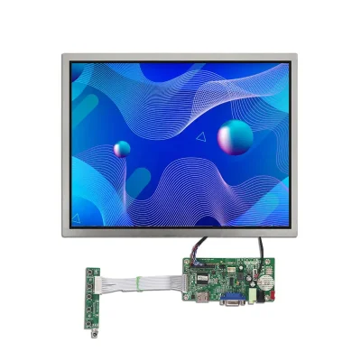
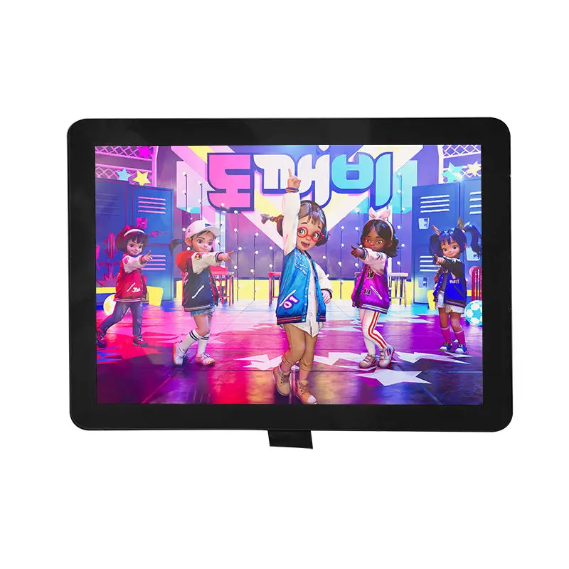
15 Inch XGA Touch Display Module Capacitive Touch for Control Panels
Model P/N
Size
Resolution
Brightness
Viewing Angle
Connector Type
Operating Temp
Overall(mm)
huisoar
HS150XA05A-V1+ CTP
Brand
Panel Size (inch)
Model P/N
Resolution
Brightness (nits)
Viewing Angle
Response Time
Overall (mm)
Active Area (mm)
Refresh Rate
Bezel Opening
Display Colors
Panel Type
Connector Type
Surface Treatment
Operating Temp
Touchscreen Type
Storage Temp
Work Mode
Pixel Format
Control Type
Maximum Power
Operating Environment
Designed For
15 Inch XGA Touch Display Module for Control Panels
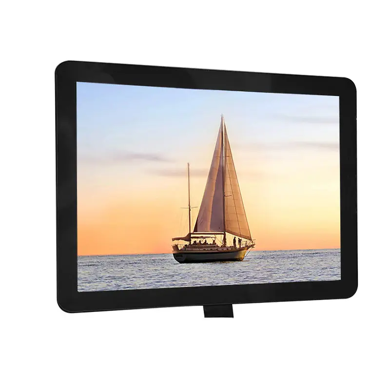
The 15 Inch XGA Touch Display Module combines a 1024 × 768 TFT LCD, LVDS image connectivity and a capacitive-touch front assembly for embedded control equipment. Its 4:3 format is well suited to operator screens that use vertical menus, alarm lists, status tables and traditional industrial interface layouts.
The LCD image path and touch-control path must be qualified separately. LVDS carries the display data, while the capacitive-touch controller requires its own confirmed interface, power, connector and host support.
Product Summary
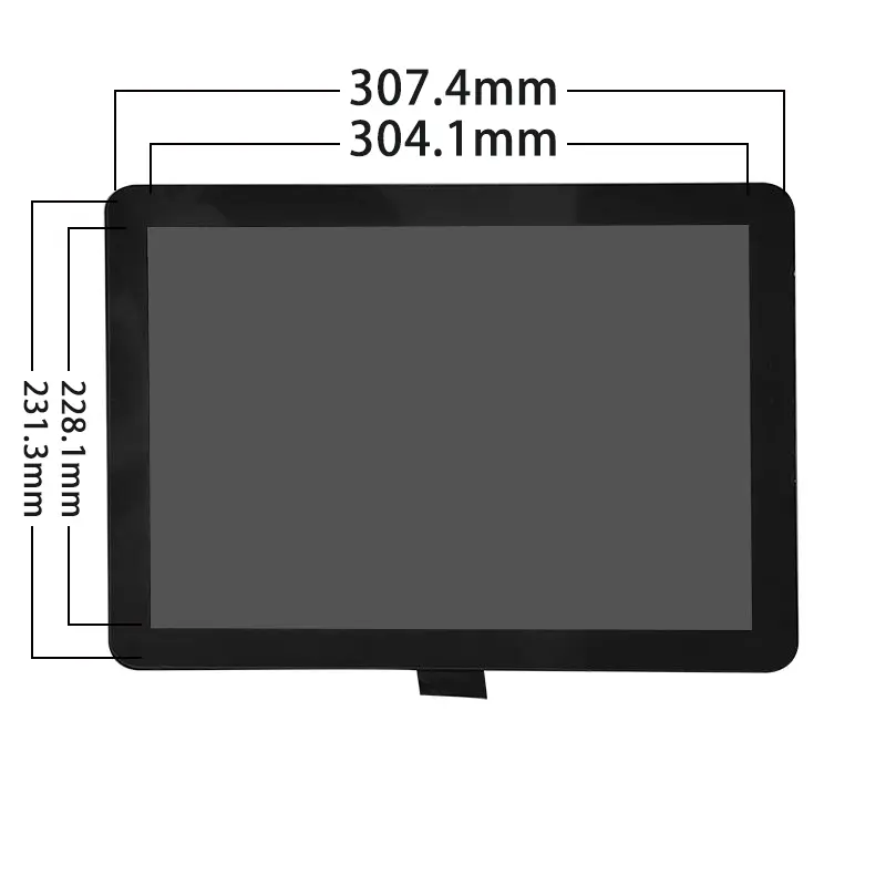
This 15-inch TFT assembly provides a 304.1 × 228.1 mm active area and a 307.4 × 231.3 mm bezel opening. The XGA pixel format gives equipment designers a practical workspace for control pages, process views, service menus and machine-state graphics.
The panel is identified as an a-Si TFT active-matrix display with a transmissive, normally black operating mode. Its anti-glare hard coating helps reduce direct surface reflections under indoor equipment lighting.
The brightness is configuration-dependent and should be confirmed for the ordered assembly. No sunlight-readable or outdoor-readability claim is implied.
Key Specifications at a Glance
The module uses a 1024 × 768 pixel arrangement with a 0.297 × 0.297 mm pixel pitch and RGB vertical stripes. The display-color information is listed as 262K / 16.2M, so the supported color depth should be confirmed against the exact LCD timing and configuration.
The module-power reference is 7.4 W. This value must be included in the host power-supply, thermal and enclosure calculations, but it does not define the complete system consumption or touch-controller load.
The operating-temperature range is −20°C to +70°C. Storage limits, humidity limits and condensation requirements should be confirmed separately.
XGA Workspace for 4:3 Control Interfaces
1024 × 768 Interface Layout
The 4:3 XGA format is useful where the interface emphasizes menus, status tables, process diagrams and vertically arranged controls rather than widescreen video content.
A 1024 × 768 user interface can support:
- alarm and event lists;
- parameter-setting pages;
- machine-state graphics;
- service and diagnostic screens;
- multilingual menu structures;
- operator instructions;
- trend and status panels.
The host must output the correct native timing and LVDS mapping. Matching the screen size and resolution does not establish compatibility.
Normally Black Anti-Glare Optics
The panel is transmissive and normally black. This optical mode should be evaluated in the complete front assembly, including the capacitive-touch sensor, cover material, adhesive or air gap, printed border and enclosure angle.
The anti-glare 3H surface is intended to reduce distracting reflections and provide a hardened outer treatment. It does not establish scratch-proof, chemical-resistant, impact-resistant or outdoor-rated performance.
The final optical stack should be tested under the intended equipment lighting.
LVDS and Capacitive-Touch Integration
LVDS Host Compatibility
A matching LVDS connector does not guarantee timing, mapping or pin compatibility.
Engineering review should cover:
- native 1024 × 768 timing;
- LVDS channel count;
- bit mapping;
- clock polarity;
- panel supply voltage;
- enable and control signals;
- backlight power and controls;
- complete pin assignment;
- connector pitch;
- contact side;
- cable orientation;
- cable length and routing.
Two 15-inch XGA panels may use different voltage rails, channel mappings, connector assignments or backlight architectures even when their physical connectors appear similar.
Touch-Control Path Qualification
The capacitive-touch system should be treated as a separate electrical subsystem.
Confirm:
- touch-controller part number;
- communication interface;
- touch supply voltage;
- touch connector and pinout;
- touch-point count;
- coordinate orientation;
- host operating-system support;
- cover-lens construction;
- controller firmware requirements;
- grounding and cable routing.
A working LVDS image does not prove that the touch system will enumerate, communicate or map coordinates correctly.
The LVDS image path and capacitive-touch control path require separate qualification.
ILI2511 Identification Boundary
ILI2511 is identified in the product information, but the available technical details do not establish its exact function in the complete assembly.
The designation does not by itself prove:
- that it drives the TFT LCD;
- that it controls the capacitive touch;
- that one IC controls both functions;
- a particular communication interface;
- host initialization requirements;
- register programming;
- supported touch-point count;
- operating-system compatibility;
- firmware behavior.
The approved IC and touch-controller documentation should be requested for the ordered configuration.
Mechanical Integration of the 15 Inch XGA Touch Display Module
Active Area and Bezel Opening
The active image area is 304.1 × 228.1 mm. The bezel opening is 307.4 × 231.3 mm.
The enclosure design should account for:
- active image visibility;
- bezel overlap;
- touch-sensor dimensions;
- cover-lens outline;
- LCD frame;
- adhesive or air-gap structure;
- cable exits;
- connector access;
- mounting pressure;
- dimensional tolerances.
The marketplace dimension of 161.0 × 107.0 mm is inconsistent with the 15-inch active area and must not be used for enclosure tooling.
Combined Assembly Drawing Requirements
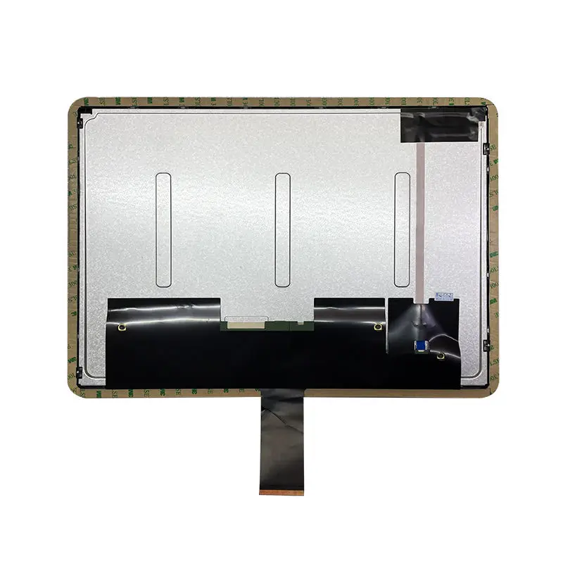
The approved combined LCD-and-touch drawing should control production release.
That drawing should identify:
- LCD outline;
- active area;
- bezel opening;
- touch-sensor outline;
- cover-lens outline;
- visible opening;
- mounting locations;
- connector positions;
- pin-1 orientation;
- cable bend zones;
- total assembly thickness;
- tolerance stack.
A bare-LCD drawing is not sufficient when the ordered item includes a capacitive-touch assembly.
Power and Temperature Boundaries
The listed module-power consumption is 7.4 W. The power architecture should separately account for:
- LCD logic power;
- backlight power;
- backlight-control circuitry;
- touch-controller power;
- host-interface losses;
- power-conversion efficiency;
- startup and peak conditions.
The listed 7.4 W module power must be included in the system power and thermal budget.
The operating range is −20°C to +70°C. This supports evaluation for industrial equipment that experiences a wider temperature range than ordinary office devices, but it does not establish outdoor, automotive, freezer, high-humidity, condensation or vibration qualification.
Temperature validation should include cold start, high-temperature image stability, touch operation, backlight behavior and enclosure heat buildup.
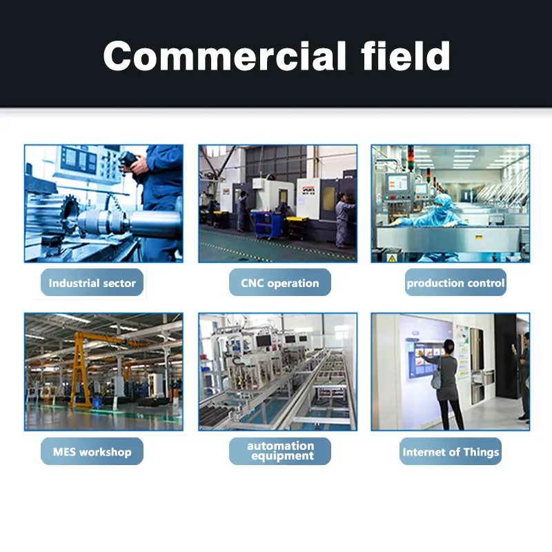
Recommended Application Routes
The module may be evaluated for:
- industrial control panels;
- factory operator terminals;
- equipment consoles;
- test and service equipment;
- compact self-service interfaces;
- machine configuration terminals;
- indoor kiosk control surfaces;
- embedded 4:3 interface systems.
These are integration routes, not certification claims. Final suitability depends on LVDS compatibility, touch-controller support, optical conditions, power design, enclosure fit and environmental testing.
Customization and Sample Qualification
Project review may cover:
- brightness target;
- capacitive-touch controller and interface;
- cover-lens geometry;
- printed borders;
- bonding structure;
- FPC shape and material;
- LVDS pin definition;
- cable orientation;
- connector selection;
- mechanical adaptation;
- packaging;
- controller-board matching.
Custom configurations are generally reviewed from 500 pieces, subject to tooling requirements, material availability and the requested specification. Sample and standard-module quantities are confirmed separately.
A representative sample should be tested for:
- native XGA image output;
- LVDS link stability;
- touch communication;
- coordinate accuracy;
- edge-touch behavior;
- cable alignment;
- backlight operation;
- power consumption;
- enclosure fit;
- optical appearance;
- temperature operation.
Procurement Checklist
Provide the following before sample or production approval:
- native 1024 × 768 timing;
- LVDS channel and mapping details;
- complete host and panel pin assignments;
- panel and backlight voltage requirements;
- connector pitch and contact side;
- LVDS cable orientation;
- touch-controller specification;
- touch communication interface;
- touch connector and pinout;
- required host or operating-system support;
- combined LCD-and-touch drawing;
- active area and bezel opening;
- cover-lens construction;
- target brightness;
- ambient-light conditions;
- system power budget;
- operating and storage temperature requirements;
- sample quantity;
- annual demand;
- validation requirements;
- production schedule.
FAQ
About 15 Inch XGA Touch Display Module
What must be checked before connecting this module to an LVDS host?
Does the LVDS connector also carry the capacitive-touch signal?
Which dimensions should control the enclosure opening?
How should the 7.4 W module-power value be used?
What is the typical lead time and production capacity?
Lead time and production capacity are For accurate information, please contact our sales team with your volume and delivery requirements; they can provide current lead times and capacity details based on your specific order.
Do you offer displays with high refresh rates (e.g., 120Hz) for smooth graphics in transportation information systems?
This product has a standard 60 Hz refresh rate. For high refresh rates like 120 Hz, we recommend discussing your application with our engineering team to evaluate if a custom solution can be developed to meet the smooth graphics needs of transportation information systems.
Can you integrate touch controllers (resistive/capacitive) into custom display modules with specific firmware requirements?
Yes, we can integrate touch controllers with specific firmware into custom display modules. For this capacitive touch panel, the touch controller requires its own confirmed interface, power, connector, and host support. Please provide your firmware requirements to our engineering team for feasibility assessment.
How does the operating temperature range of your industrial panels (e.g., -30°C to 80°C) affect long-term performance and warranty?
The operating temperature range for this panel is -20°C to 70°C, with storage from -30°C to 80°C. Operating within these limits ensures reliable long-term performance. Extended use beyond these ranges may affect display stability and warranty; we recommend confirming your environmental conditions with our support team.
What are the operating temperature ranges for your industrial LCD panels, especially for extended outdoor use?
This panel operates from -20°C to 70°C and stores from -30°C to 80°C. For extended outdoor use, ensure the ambient temperature stays within these limits. If your application requires wider ranges, please consult our engineering team to discuss possible customizations.
Can you customize the mechanical dimensions and mounting holes for a specific industrial enclosure?
Mechanical dimensions and mounting holes can be customized for specific enclosures. Please provide your enclosure drawings and mounting requirements to our engineering team for a feasibility review and custom design proposal.
Freya Yang
+86 18318948097