Freya Yang
+86 18318948097
+852 62667476
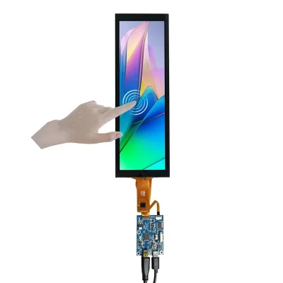
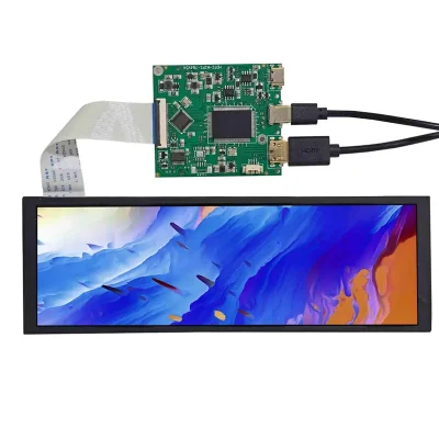
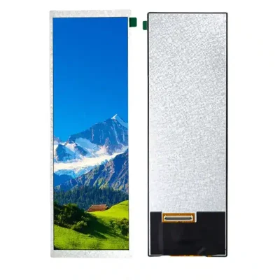
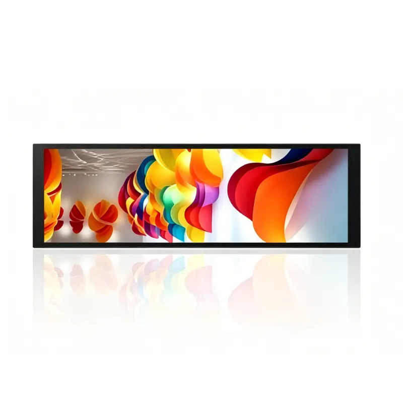
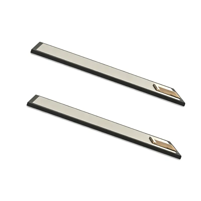
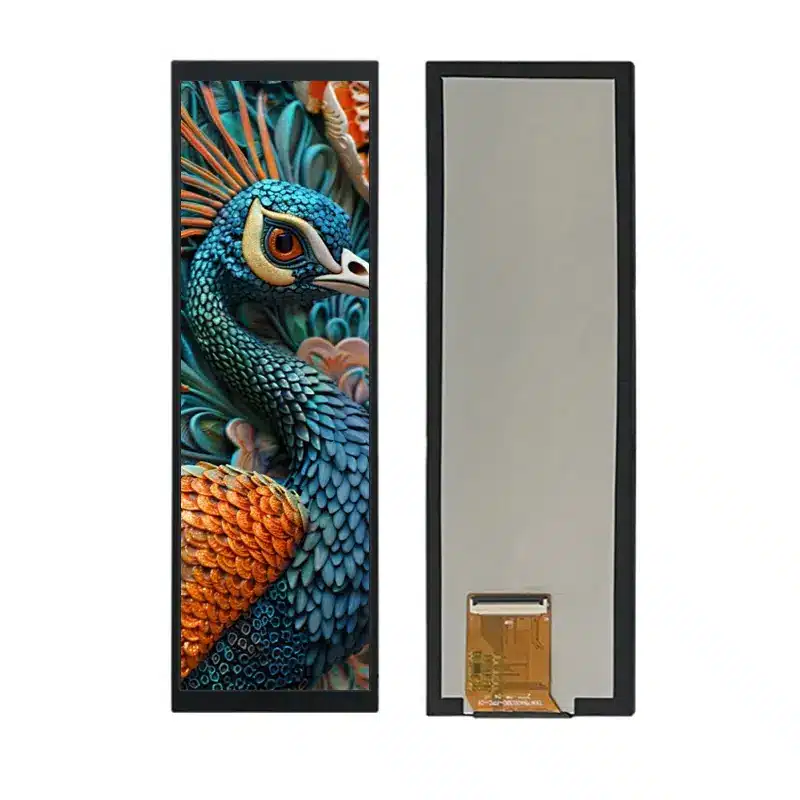
7.84 Inch Motorcycle Status Navigation Interface Display Module
Model P/N
Size
Resolution
Brightness
Viewing Angle
Connector Type
Operating Temp
Overall(mm)
huisoar
HS784003B0
Brand
Panel Size (inch)
Model P/N
Resolution
Brightness (nits)
Viewing Angle
Contrast Ratio
Response Time
Overall (mm)
Active Area (mm)
Refresh Rate
Display Colors
Panel Type
Connector Type
Operating Temp
Touchscreen Type
Storage Temp
Work Mode
Operating Environment
Designed For
7.84 Inch Motorcycle Status Navigation Interface Display Module
The Motorcycle Status Navigation Interface Display Module combines a tall IPS panel, 700 cd/m² luminance and a 40-pin MIPI connection for vertical vehicle HMI layouts.
Product Summary
The Motorcycle Status Navigation Interface Display Module provides a narrow portrait display area for motorcycle instruments, electric-vehicle dashboards and compact navigation interfaces. Its elongated geometry supports vertically arranged speed data, operating status, warning messages, route guidance and system controls without requiring the width of a conventional landscape panel.
The 7.84-inch module offers a 59.4 × 190.08 mm active area inside a 67.14 × 205.12 × 4.5 mm outline. It combines IPS viewing, 700 cd/m² typical luminance, an 800:1 typical contrast ratio and a 40-pin MIPI connection. The standard configuration is non-touch.
Key Specifications
| Parameter | Value |
|---|---|
| Display size | 7.84 inch |
| Target resolution | 480 × 1280 pixels |
| Resolution qualification | 400 × 1280 is also recorded and must be resolved |
| Panel type | IPS a-Si TFT-LCD |
| Optical structure | Transmissive |
| Luminance | 700 cd/m² typical |
| Contrast ratio | 800:1 typical |
| Viewing angle | 80/80/80/80, L/R/U/D |
| Display colors | 16.7M |
| Pixel arrangement | RGB stripe |
| Interface | 40-pin MIPI |
| Active area | 59.4 × 190.08 mm |
| Overall size | 67.14 × 205.12 × 4.5 mm |
| Backlight | WLED |
| Touch | Non-touch |
| Operating temperature | −20°C to +70°C |
| Storage temperature | −30°C to +80°C |
Resolution Confirmation Before Host Release
480 × 1280 Target Configuration
The target configuration is 480 × 1280 pixels. This raster creates a tall display canvas for vertically stacked instrument and navigation content.
A typical layout may allocate areas for:
- vehicle speed
- battery or fuel status
- operating mode
- warning indicators
- route guidance
- turn instructions
- communication status
- trip information
- temperature data
- system menus
The host, boot graphics and interface assets should be prepared only after the native raster has been formally approved.
Why the 400 × 1280 Record Matters
Technical records also list 400 × 1280 for the same general mechanical format. The two raster definitions are not interchangeable.
A host configured for the wrong width may produce:
- no image
- cropped content
- incorrect scaling
- shifted timing
- distorted UI geometry
- unstable output
The approved panel document must identify the native pixel matrix and timing before the controller, FPC or software image is released.
Vertical Motorcycle Interface Design
Status and Navigation Content Zones
The tall format supports information arranged from top to bottom. A motorcycle or electric-vehicle interface may divide the screen into fixed sections for speed, route guidance, battery state, warnings and ride data.
This layout can reduce horizontal enclosure width while retaining enough vertical space for several information blocks. It is particularly useful for narrow dashboard structures, center-mounted instrument areas and side-console displays.
Native-Raster UI Preparation
The interface should be designed directly for the approved native raster.
Validate:
- portrait orientation
- font scaling
- icon dimensions
- warning visibility
- route-map scaling
- content-safe margins
- boot-screen layout
- camera-image handling
- language expansion
- day and night themes
Rotating an existing landscape UI without redesign can create inconsistent spacing and difficult-to-read information.
IPS Optical Performance
700 cd/m² Luminance Boundary
The panel is specified at 700 cd/m² typical luminance. This supports evaluation in bright vehicle cabins, motorcycle dashboards and other higher-ambient-light installations.
A 700 cd/m² panel does not by itself establish finished-system sunlight readability behind cover glass.
Final visibility also depends on:
- cover-lens transmission
- surface reflections
- air-gap construction
- optical bonding
- installation angle
- direct daylight
- enclosure shading
- thermal conditions
Representative samples should be evaluated with the intended lens and housing.
Viewing Angle, Contrast and Color
The panel provides 80/80/80/80 viewing angles in left, right, upper and lower directions. This supports viewing when the rider or operator is not positioned directly in front of the screen.
The 800:1 typical contrast ratio supports separation between backgrounds, status values, navigation graphics and warning colors. The RGB-stripe arrangement and 16.7M-color capability provide a suitable basis for graphical HMI content, but they do not establish calibrated color accuracy.
40-Pin MIPI Host Integration
Lane, Timing and Pinout Qualification
A 40-pin MIPI connector does not guarantee lane, timing, voltage, initialization or pin compatibility with another panel.
Before designing the FPC or applying power, confirm:
- approved native resolution
- MIPI DSI lane count
- video or command mode
- lane speed
- complete 40-pin assignment
- connector pitch
- contact side
- FPC orientation
- panel logic voltage
- reset signals
- backlight voltage and current
- backlight enable and dimming
- cable length and routing
A host that supports MIPI DSI generally is not automatically compatible with this panel.
Initialization and Power Documentation
The engineering package should include:
- initialization commands
- native timing
- reset timing
- power sequence
- sleep and wake behavior
- orientation settings
- backlight-control definition
- error-recovery requirements
Initialization data from another 7.84-inch MIPI panel should not be copied without verification. Panels with similar size and resolution can use different controllers, voltages and pin assignments.
Motorcycle Status Navigation Interface Display Module Mechanics
Active Area and Front Opening
The active area measures 59.4 × 190.08 mm. This value should guide:
- visible bezel opening
- cover-lens window
- printed black mask
- display alignment
- UI-safe margins
- warning-icon placement
- navigation-content boundaries
Critical speed, warning and battery information should remain inside the approved visible opening after bezel overlap and assembly tolerances are included.
Outline and FPC Clearance
The complete module measures 67.14 × 205.12 × 4.5 mm.
Mechanical review should confirm:
- active-area position
- FPC exit
- connector location
- cable bend radius
- rear clearance
- mounting support
- cover-lens overlap
- enclosure tolerances
- service access
- vibration-management requirements
The precise dimensional values should control tooling rather than rounded 67 × 205 × 4 mm references.
Temperature Qualification
The panel is specified for operation from −20°C to +70°C and storage from −30°C to +80°C.
These temperature limits support evaluation in vehicle and embedded-equipment environments, but they do not independently establish automotive or motorcycle qualification.
System testing should consider:
- cold startup
- hot-dashboard operation
- backlight performance across temperature
- controller temperature
- enclosure heat
- condensation
- FPC flexibility
- vibration and shock
- repeated thermal cycling
Qualification should use the final controller, optical stack and enclosure.
Non-Touch Vehicle HMI Architecture
The standard module is non-touch. This suits systems where input is provided through:
- handlebar switches
- physical dashboard buttons
- rotary controls
- vehicle-control networks
- an external keypad
- a separately developed touch assembly
Potential applications include:
- motorcycle instrument panels
- electric-vehicle dashboards
- navigation screens
- ride-status interfaces
- smart-appliance displays
- industrial control columns
- narrow equipment panels
A non-touch construction avoids the optical loss, controller requirements and added thickness of an integrated touch stack.
Custom Integration Options
Project review may include:
- resolution and timing confirmation
- MIPI host matching
- custom 40-pin FPC
- initialization verification
- brightness evaluation
- cover-lens sizing
- anti-glare or anti-reflection treatment
- optical bonding
- enclosure adaptation
- FPC routing
- branding
- optional touch development
- packaging and labeling
Custom configurations are generally reviewed from 500 pieces, subject to tooling requirements, material availability and the requested specification. Sample and standard-module quantities are confirmed separately.
Customization for the Motorcycle Status Navigation Interface Display Module should begin only after the approved resolution, interface package and mechanical drawing are available.
Procurement Checklist
Before requesting samples or approving production, submit or confirm:
- ordered native resolution
- complete native timing
- MIPI DSI lane count
- video or command mode
- lane speed
- complete 40-pin assignment
- connector pitch
- contact side and FPC orientation
- panel logic voltage
- backlight voltage and current
- approved initialization data
- reset and power sequence
- 67.14 × 205.12 × 4.5 mm enclosure fit
- 59.4 × 190.08 mm active-area position
- cover-glass stack
- 700 cd/m² lighting target
- operating-temperature requirements
- non-touch or optional-touch architecture
- sample quantity
- annual demand
- production schedule
Sample approval should precede controller release, FPC manufacture, cover-lens tooling and enclosure production.
FAQ
About 7.84 Inch Motorcycle Status Navigation Interface Display Module
Which resolution should the host use?
What must be checked before connecting a 40-pin MIPI host?
Does 700 cd/m² guarantee daylight readability?
Which dimensions should control enclosure release?
When should the non-touch configuration be selected?
Freya Yang
+86 18318948097