
~
~
~
~
~
~
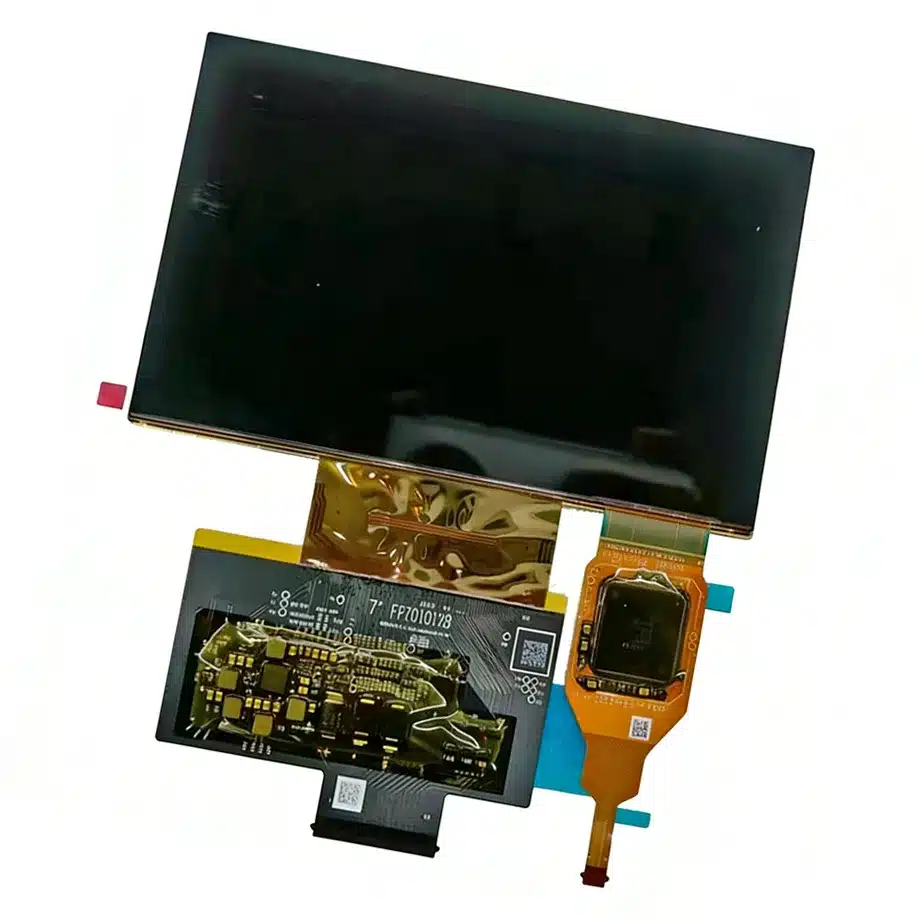
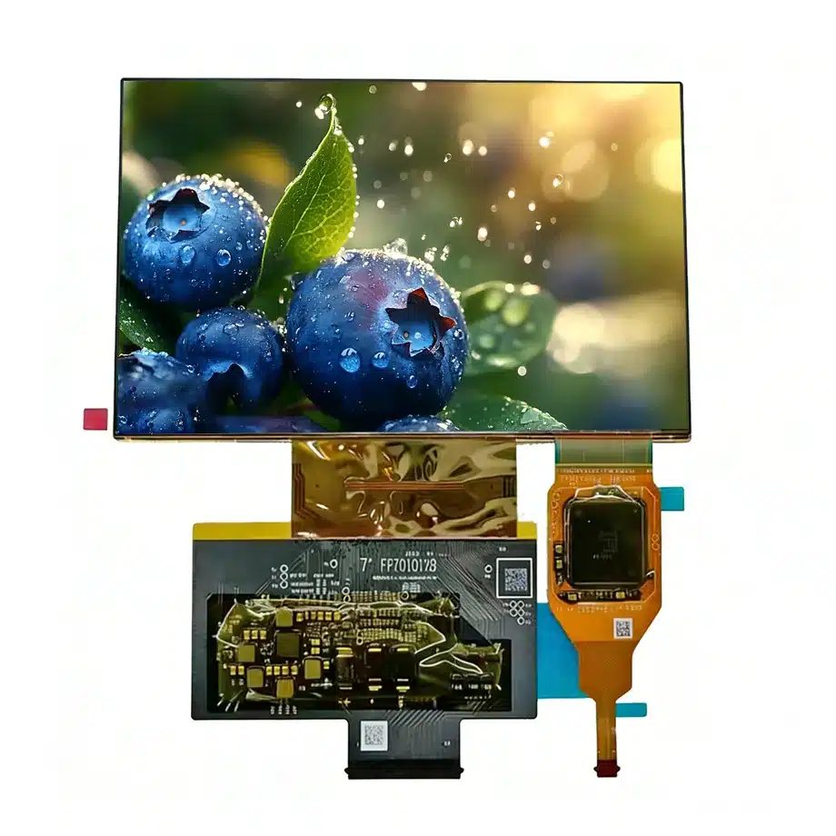
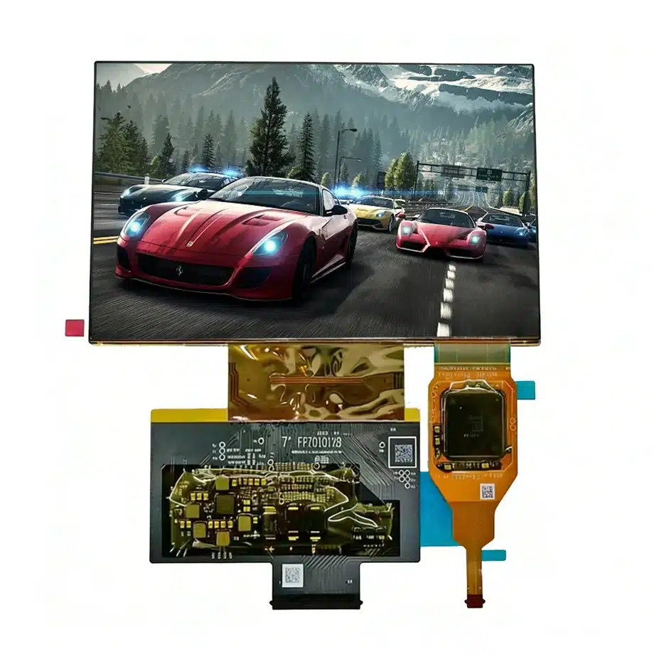
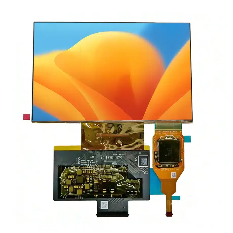
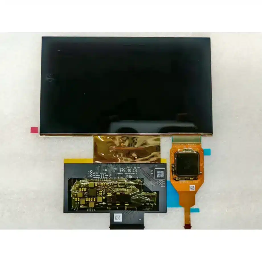
G700FCP63.A Automotive On-Cell AMOLED LVDS Display 7in EDO
Model P/N
Size
Resolution
Brightness
Viewing Angle
Connector Type
Operating Temp
Overall(mm)
edo
G700FCP63.A
Brand
Panel Size (inch)
Model P/N
Resolution
Brightness (nits)
Viewing Angle
Contrast Ratio
Response Time
Overall (mm)
Active Area (mm)
Refresh Rate
Display Colors
Panel Type
Connector Type
Operating Temp
Touchscreen Type
Storage Temp
Work Mode
Pixel Format
Input Voltage (V)
Touch Interface
Designed For
Product Details
The G700FCP63.A Automotive On-Cell AMOLED LVDS Display is a 7.0-inch EDO AM-OLED full module with explicit current-run application evidence for automotive displays and outdoor high-brightness use. It combines a 1920×1080 FHD image, 700 cd/m² typical luminance, 100000:1 minimum contrast, 100% DCI-P3 wording, on-cell touch over I²C and a -40 to 85 °C operating range. The OLED is self-emissive, uses built-in RM69C00/S7883 driver IC references, and accepts dual-channel 8-bit LVDS through a 60-pin 0.5 mm FPC.
This is not a generic consumer OLED. The automotive, wide-temperature and high-brightness evidence creates a more demanding integration context, while the presence of on-cell touch adds a second functional path that must be validated alongside the image link. System engineers should keep vehicle electrical conditions, optical readability, touch behavior and thermal management separate from the component facts; the panel evidence supports evaluation, not a blanket automotive qualification or environmental certification.
Three buyer value propositions
Wide -40 to 85 °C operating range for vehicle-oriented integration
The supplied exact-model data explicitly supports -40 to 85 °C operation and identifies automotive display use. That gives vehicle-interface teams a documented component boundary for cold-start and hot-cabin testing. The finished unit still requires its own vehicle, EMC, mechanical and reliability qualification.
700-nit self-emissive AMOLED with 100% DCI-P3 wording
The module combines OLED contrast behavior with 700 cd/m² typical luminance and 100% DCI-P3 wording. These are useful optical facts for a compact high-ambient interface. Final sunlight readability depends on cover materials, reflections, mounting angle and system brightness policy, so the outdoor claim must remain configuration-aware.
Integrated on-cell touch over I²C
Touch is part of the exact configuration, not an optional inference. I²C communication should be validated as a separate subsystem from the LVDS display path. This gives sourcing a single display/touch module identity while requiring firmware, grounding and edge-response testing in the finished assembly.
Key Specifications at a Glance
| Brand | EDO |
|---|---|
| Model P/N | G700FCP63.A |
| Size | 7.0 inch |
| Resolution | 1920(RGB)×1080, FHD, 16:9 |
| Active Area | 155.06(W)×87.221(H) mm |
| Overall | 160.56×93.72×2.24 mm |
| Brightness | 700 cd/m² (Typ.) |
| Viewing Angle | 85/85/85/85 (Min.)(CR≥1000) |
| Display Colors | 16.7M, 100% DCI-P3 |
| Refresh Rate | 60 Hz |
| Connector / Native Interface | LVDS (2 ch, 8-bit), 60 pins 0.5 mm FPC |
| Input Voltage | 3.3/4.6/-4.3 V (Typ.)(VCC/ELVDD/ELVSS) |
| Operating Temperature | -40 ~ 85 °C |
| Storage Temperature | -40 ~ 90 °C |
| Panel Type | AM-OLED, OLED (Full Module) |
| Pixel Format | Sub-Pixel Rendering |
| Contrast Ratio | 100000:1 (Min.) |
| Response Time | 3 ms (Typ.)(Tr+Td) |
| Backlight / Emission | Self-emissive OLED, 10,000 hours |
| Designed For | Automotive displays and outdoor high-brightness interfaces; wide-temperature on-cell-touch OLED applications subject to vehicle/system qualification |
| Touchscreen Type | On-Cell Touch |
| Touch Interface | I²C |
How should the LVDS and touch paths be separated in the schematic?
Treat the 60-pin dual-channel 8-bit LVDS display interface and the I²C touch interface as different functions with their own bring-up checks. Confirm LVDS timing, pin mapping and power rails for the image path; then verify touch-controller addressing, reset/interrupt behavior and coordinate orientation. After both pass independently, test them together under rapid touch input and changing image content. Shared power or grounding can create interactions that do not appear in isolated bench tests. Preserve the exact module and touch-controller assumptions in the BOM.
What does the -40 to 85 °C operating range require in practice?
Cold-start testing should include image appearance, response behavior, touch response and power-up recovery after a full low-temperature soak. At the hot end, test sustained high brightness with realistic vehicle-cabin or enclosure heating while monitoring local module temperature. The storage range extends to -40 to 90 °C, but storage survival and powered operation are different conditions. These component boundaries do not by themselves establish automotive-grade certification; the complete display unit must meet the vehicle program's environmental and reliability plan.
How should outdoor high-brightness evidence be translated into a vehicle display?
The current-run evidence explicitly names Outdoor High Brightness and provides 700 cd/m² typical luminance. That supports high-ambient evaluation, but the finished optical stack determines whether the user can actually read the display in direct sun. Measure the module behind the intended cover lens or protective window, including reflections and any optical bonding. Check polarized-sunglasses behavior at relevant angles if it matters to the vehicle application. Avoid describing 700 nits alone as a guarantee of sunlight readability.
AMOLED power rails and built-in driver IC considerations
The supplied electrical record lists 3.3/4.6/-4.3 V for VCC/ELVDD/ELVSS and identifies built-in RM69C00/S7883 driver IC references. Verify the exact rail sequencing, ripple and transient behavior with the production power design. OLED current demand varies with displayed content, so a dark test screen is not a worst-case power test. Include bright full-screen patterns and rapid content changes when measuring supply stability. Do not substitute a generic LCD power design merely because the host image interface is LVDS.
On-cell touch validation after mechanical assembly
Touch performance should be accepted after the OLED is mounted in the real housing. Grounding, conductive brackets, bezel pressure and any cover lens can influence sensitivity or false-touch behavior. Build a touch grid that includes corners and edges, then repeat at temperature extremes and representative brightness levels. The same-model source indicates on-cell touch with I²C, but it does not define every host firmware condition. Keep the approved touch firmware and calibration context with the display module record.
Color and contrast claims for a self-emissive display
The exact facts support 100000:1 minimum contrast, 100% DCI-P3 wording and 16.7M colors. Those values describe the panel, not the color calibration of the finished vehicle interface. If the program has brand-color, night-mode or warning-color requirements, measure them at the system level under controlled conditions. OLED black level and contrast can be strong, but reflections from the outer cover can dominate perceived contrast in daylight. Keep component optical claims separate from finished-product marketing or certification statements.
Mechanical package and AI-bracket context
The module outline is 160.56×93.72×2.24 mm around a 155.06×87.221 mm active area. The same-model description references an AI bracket, but bracket geometry or mounting compatibility should not be generalized without the exact drawing. Review FPC bend radius, support points, pressure on the OLED stack and thermal paths in the real housing. A thin self-emissive module needs controlled support; a service replacement should not be approved from active-area dimensions alone.
Automotive sourcing without unsupported grade claims
The user evidence directly supports the Automotive Display taxonomy, but it does not establish AEC qualification, functional-safety status or a specific OEM approval. Procurement should release the part against the exact EDO identity, electrical interface, touch configuration, temperature range and approved mechanical stack. Keep vehicle-program qualifications in a separate document set. If another 7-inch AMOLED is proposed, compare touch architecture, FPC, power rails, driver IC behavior, thermal limits and optical stack before treating it as an alternate.
Cold-crank, restart and brownout scenarios
Vehicle-oriented electronics can experience supply disturbances that a laboratory bench supply does not reproduce. Use the system power architecture to test controlled brownout, restart and recovery while observing both OLED image and touch behavior. The component data does not define a vehicle transient standard, so the exact test levels belong to the finished product requirements. The engineering objective is to verify that the panel rails and touch controller recover predictably and that no persistent blank, corrupted image or unresponsive touch state remains after the host returns to normal power.
OLED content loading and thermal characterization
Self-emissive power varies with image content. Measure representative dark UI, mixed navigation graphics and bright high-area content while monitoring the OLED power rails and module temperature. This is important when evaluating 700-nit operation near the upper temperature limit. Do not infer a fixed power number from an LCD-style backlight model. If the vehicle UI uses automatic day/night themes, qualify both conditions because they can create different electrical and thermal loads even at the same nominal brightness setting.
First-article evidence for an integrated automotive-touch module
The approval package should identify the exact EDO model, LVDS/FPC definition, power rails, touch I²C configuration, host firmware, mechanical bracket/cover stack and representative thermal results. Include a touch-grid test after assembly and at least one high-ambient readability evaluation. Store the result with the vehicle program rather than relying on a supplier marketplace description. This makes later sourcing review auditable and preserves the distinction between component evidence and system qualification.
Production regression triggers for display and touch
A change to host firmware, touch firmware, cover lens, power supply or mounting bracket should trigger focused regression instead of automatic acceptance. Firmware changes deserve display/touch recovery tests; a cover-stack change deserves readability and touch-edge checks; a power redesign deserves rail-sequencing and brownout recovery; a bracket change deserves pressure and FPC-clearance review. Recording these triggers with the approved module keeps the automotive-oriented integration controlled without claiming that the component itself certifies the finished vehicle system.
Evidence and engineering references
For exact-model traceability, retain G700FCP63.A on Panelook. For LVDS signal-engineering background, Texas Instruments LVDS resources provide industry context; vehicle qualification remains system-specific.
Engineering and sourcing review
For release, keep G700FCP63.A tied to the exact current-run fact set, approved drawing or first article, native interface definition, power sequence, optical acceptance and the target system configuration. Replacement approval should be evidence-based and model-specific; shared size, resolution, connector count or family name is not sufficient proof of interchangeability.
Recommended: Same Size
(7")
Applications & Value of LCD Panel

- Fast sourcing with in-stock panels & cross-reference alternatives
- Stable supply chain with long-term availability
- Engineering-level support from panel to integration
- Custom solutions: cable, touch & optical bonding
- Strict quality control with IQC / OQC / aging test
- Full traceability system for quality assurance
- Complete technical documentation & drawings
- Compliance support: RoHS & certification files
