
~
~
~
~
~
~
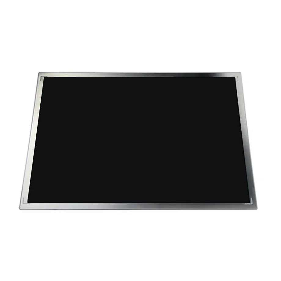
ET101WSM-N90 Healthcare 34-Pin LVDS WSVGA Module 10.1in BOE
Model P/N
Size
Resolution
Brightness
Viewing Angle
Connector Type
Operating Temp
Overall(mm)
boe
ET101WSM-N90
Brand
Panel Size (inch)
Model P/N
Resolution
Brightness (nits)
Viewing Angle
Contrast Ratio
Response Time
Overall (mm)
Active Area (mm)
Refresh Rate
Display Colors
Panel Type
Connector Type
Surface Treatment
Operating Temp
Touchscreen Type
Storage Temp
Work Mode
Pixel Format
Input Voltage (V)
Weight (g)
Designed For
Product Details
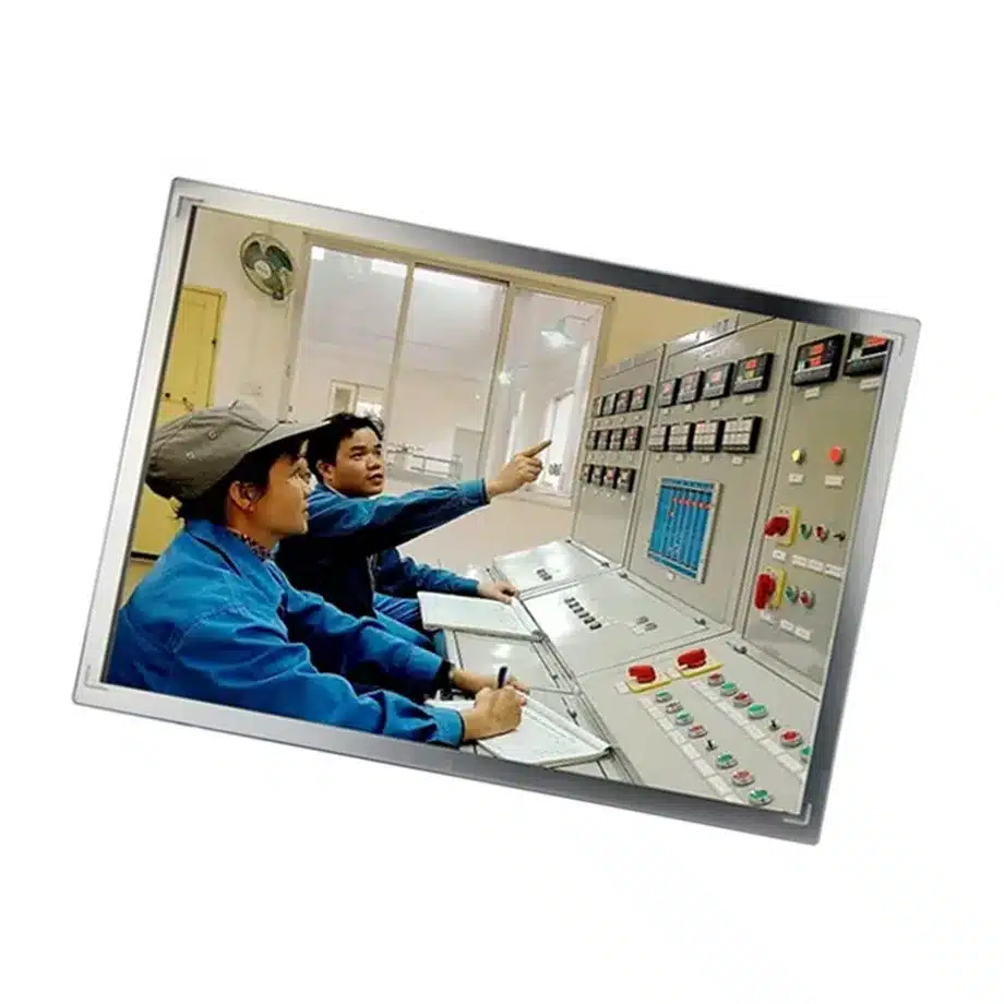
The ET101WSM-N90 Healthcare 34-Pin LVDS WSVGA Module is a 10.1-inch BOE a-Si TFT-LCD module whose user-supplied application evidence explicitly names industrial and healthcare equipment. The exact configuration uses 1024×600 WSVGA resolution, single-channel 6/8-bit LVDS through a 34-pin 0.5 mm FPC, 350 cd/m² typical luminance and a WLED backlight without an integrated driver. The panel also uses multiple supply rails—3.3/10.8/21/-8.0 V for VDD/AVDD/VGH/VGL—so controller and power-board design must be based on the exact electrical definition rather than on generic 3.3 V LCD assumptions.
The module is a conventional TN, normally-white transmissive design with 600:1 typical contrast and asymmetric viewing angles. Those facts make viewing orientation, backlight drive and enclosure geometry more important than they would be for a wide-view IPS-class panel. For industrial or healthcare equipment, the safe purchasing approach is to qualify the component inside the final HMI or instrument and keep the exact LVDS/FPC and power design with the approved BOM.
Three buyer value propositions
Explicit industrial and healthcare application evidence
The current-run parameters directly identify Industrial and Healthcare use. That supports evaluation for embedded equipment in those sectors without implying medical certification, patient-contact approval or a particular regulatory class. The practical value is a documented application starting point for system designers.
34-pin LVDS with a simple 1024×600 timing target
A single-channel 6/8-bit LVDS interface and WSVGA native image can fit embedded controllers that still use conventional LVDS panel outputs. The exact 34-pin FPC mapping, 60 Hz timing and multi-rail power sequence must be preserved; a generic WSVGA controller is not automatically compatible.
Separate backlight-driver responsibility
The WLED backlight is supplied without an integrated driver. This gives the equipment designer control over LED power, dimming and enable behavior, but it also creates a clear design responsibility. The LED-driver circuit must be qualified separately from the panel's logic and gate/source supply rails.
Key Specifications at a Glance
| Brand | BOE |
|---|---|
| Model P/N | ET101WSM-N90 |
| Size | 10.1 inch |
| Resolution | 1024(RGB)×600, WSVGA, 16:9 |
| Active Area | 222.72(W)×125.28(H) mm |
| Overall | 235.3×143×5.1 mm |
| Brightness | 350 cd/m² (Typ.) |
| Viewing Angle | 80/80/60/70 (Typ.)(CR≥10) |
| Display Colors | 262K/16.7M, 49% NTSC |
| Weight | 196 g (Typ.) |
| Refresh Rate | 60 Hz |
| Connector / Native Interface | LVDS (1 ch, 6/8-bit), 34 pins 0.5 mm FPC |
| Input Voltage | 3.3/10.8/21/-8.0 V (Typ.)(VDD/AVDD/VGH/VGL) |
| Operating Temperature | 0 ~ 60 °C |
| Storage Temperature | -20 ~ 60 °C |
| Panel Type | a-Si TFT-LCD, LCM |
| Pixel Format | RGB Vertical Stripe |
| Surface Treatment | Antiglare |
| Contrast Ratio | 600:1 (Typ.) |
| Response Time | 25 ms (Typ.)(Tr+Td) |
| Work Mode | TN, Normally White, Transmissive |
| Backlight / Emission | WLED, no integrated driver |
| Maximum Power | 2.16 W (Typ.) |
| Designed For | Industrial and healthcare display equipment; landscape or portrait WSVGA embedded interfaces subject to system qualification |
| Touchscreen Type | Without touch screen |
How should the 34-pin LVDS interface be brought up?
Start with the exact FPC pin assignment, 1024×600 timing and 6/8-bit mapping. Verify clock/data polarity, panel-enable timing and each required supply rail before attaching the final cable. The panel logic is not described by a single 3.3 V input; the supplied record lists VDD, AVDD, VGH and VGL rails. Scope the power-up and power-down sequence during first article, especially if the controller board generates the higher and negative voltages locally. A display that shows an image on the bench can still suffer reliability or startup issues if sequencing is outside the exact-model requirements.
What does 'no integrated backlight driver' mean for the system?
The system must provide the LED-driver function. Confirm the exact WLED voltage/current requirements from the approved model documentation, then design current regulation, dimming, enable, protection and fault behavior around those limits. Do not reuse the 3.3 V logic value as a backlight assumption. During qualification, measure LED current and panel luminance across the intended brightness range and temperature. If the driver circuit is later changed, rerun optical and thermal checks because two electrically similar drivers can produce different dimming curves or startup behavior.
How should TN viewing direction affect enclosure design?
The panel is normally white with a 6 o'clock preferred viewing direction and asymmetric 80/80/60/70 viewing-angle data. Mount the sample in the actual operator orientation and evaluate text, alarms, grayscale and color from the expected standing or seated positions. Landscape and portrait use are possible in the same-model application record, but rotating a TN panel changes which viewing direction becomes most critical. The enclosure design should be released only after the operator-viewing geometry is tested, especially for equipment where an alert must remain legible from an off-axis position.
Healthcare application wording without overclaiming
The user-supplied application says Healthcare, which is sufficient for the inventory taxonomy and for discussing healthcare equipment integration. It is not evidence of IEC 60601 compliance, diagnostic-display performance, sterilization resistance or any other certification. A healthcare product team should qualify brightness, viewing angle, cleaning environment, EMC and electrical isolation at the finished-device level. Public copy should keep the claim at 'healthcare display equipment' unless separate documentation supports a narrower regulated use.
Industrial temperature and enclosure thermal planning
The documented operating range is 0 to 60 °C, with storage from -20 to 60 °C. For an industrial HMI, measure the actual panel cavity temperature under maximum processor and backlight load rather than using room ambient as the design input. A sealed enclosure, nearby power supply or limited airflow can raise internal temperature. At the low end, check startup image stability and backlight behavior after soak. The component range provides boundaries for qualification but does not create an industrial certification by itself.
Mechanical fit around a 235.3×143×5.1 mm module
The active area is 222.72×125.28 mm inside a 235.3×143×5.1 mm outline. Check bezel opening, FPC exit, rear clearance and mounting support against the exact drawing. The 196 g typical mass is modest, but cable strain can still damage a fine-pitch FPC if the enclosure does not provide retention. For portrait use, review cable routing and gravity direction separately. Preserve the physical drawing with the controller board design so a later WSVGA panel is not accepted solely because the active area appears similar.
Optical acceptance for 350-nit WSVGA equipment
Use 350 cd/m² typical luminance, 600:1 typical contrast and 49% NTSC wording as the component baseline. These figures support ordinary indoor equipment use; they do not justify sunlight-readable or wide-gamut claims. Test the final protective window, air gap or touch overlay if the equipment adds one. Such layers can reduce luminance and alter reflections. If an instrument needs a minimum brightness at the user surface, specify and measure that system-level value instead of assuming the bare-panel number transfers unchanged.
Sourcing controls for an embedded legacy-interface panel
Store the exact BOE model, 34-pin FPC definition, LVDS timing, supply rails, separate LED-driver design and mechanical drawing with the product BOM. If a future alternate uses eDP, a different LVDS connector or an integrated backlight driver, treat it as a redesign even when the size and resolution match. Controlled replacement work should compare electrical architecture first, then optics and mechanics. This discipline is especially important for long-lived industrial and healthcare equipment where controller boards may remain in service for many years.
Power-sequence documentation for serviceability
Because ET101WSM-N90 uses several panel rails and a separate backlight driver, the service package should include the approved power sequence and test points. Label which rail is VDD, AVDD, VGH and VGL, and document the LED-driver enable/dimming path separately. During fault diagnosis, this prevents technicians from treating a missing image as a generic 3.3 V panel problem. It also makes controller-board redesign safer because engineers can verify that new DC/DC stages reproduce the original sequence and voltage behavior before connecting the display.
Portrait and landscape validation for a TN module
The same-model description mentions landscape/portrait use, but TN viewing behavior means the two orientations should not be assumed equivalent. Rotate the actual assembly, then repeat off-axis readability checks for text, grayscale, alarms and any critical UI elements. Cable exit and FPC strain may also change in portrait orientation. If the product family supports both orientations, keep separate mechanical and optical acceptance notes. This is especially useful in industrial terminals or healthcare carts where the installation angle can change between deployments.
First-article package for long-lived embedded equipment
For first article, retain the exact BOE label, LVDS timing, 34-pin FPC, power-sequence waveform, LED-driver design, mechanical drawing and operator-viewing test. Add chamber results if the equipment uses the upper or lower portion of the 0 to 60 °C operating range. Document the protective window or touch overlay used in the final device because it can change brightness and glare. Long-lived equipment benefits from this record when the original controller board or backlight driver is revised years later.
Evidence and engineering references
The current-run source is ET101WSM-N90 on Panelook. For LVDS interface engineering background, consult Texas Instruments LVDS resources; exact pin mapping still comes from the panel documentation.
Engineering and sourcing review
For release, keep ET101WSM-N90 tied to the exact current-run fact set, approved drawing or first article, native interface definition, power sequence, optical acceptance and the target system configuration. Replacement approval should be evidence-based and model-specific; shared size, resolution, connector count or family name is not sufficient proof of interchangeability.
Recommended: Same Size
(10.1")
Applications & Value of LCD Panel

- Fast sourcing with in-stock panels & cross-reference alternatives
- Stable supply chain with long-term availability
- Engineering-level support from panel to integration
- Custom solutions: cable, touch & optical bonding
- Strict quality control with IQC / OQC / aging test
- Full traceability system for quality assurance
- Complete technical documentation & drawings
- Compliance support: RoHS & certification files
