Freya Yang
+86 18318948097
+852 62667476
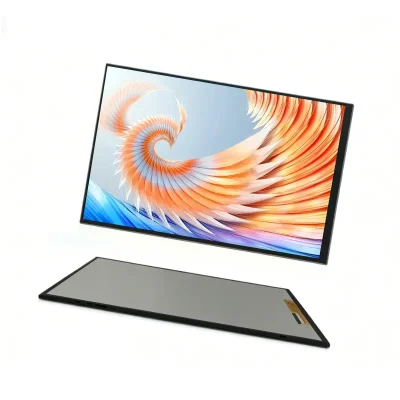
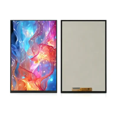
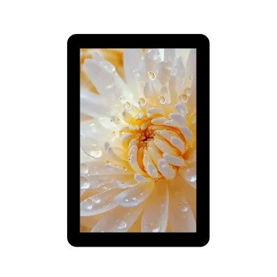
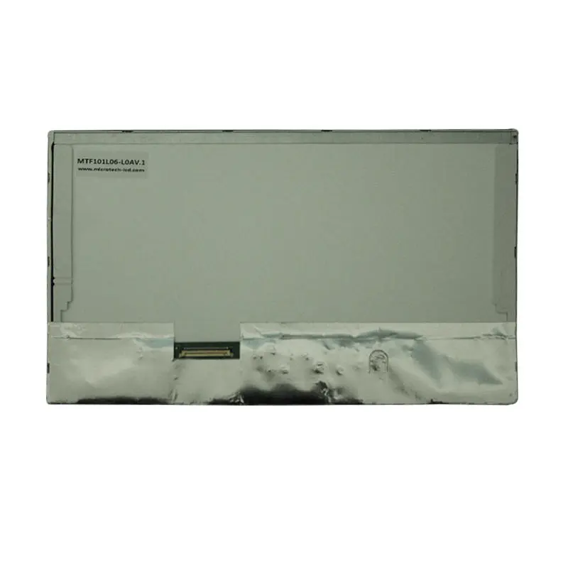
10.1 Inch LVDS Touchscreen Panel Capacitive Touch for Industrial HMI

Model P/N
Size
Resolution
Brightness
Viewing Angle
Connector Type
Operating Temp
Overall(mm)
huisoar
HS101L06-L0A
Brand
Panel Size (inch)
Model P/N
Resolution
Brightness (nits)
Viewing Angle
Contrast Ratio
Response Time
Overall (mm)
Active Area (mm)
Refresh Rate
Display Colors
Panel Type
Connector Type
Surface Treatment
Operating Temp
Touchscreen Type
Storage Temp
Work Mode
Pixel Format
Control Type
Protective Glass Specification
Operating Environment
Motherboard Type
Designed For
10.1 Inch LVDS Touchscreen Panel for Industrial HMI
A landscape 1024×600 capacitive-touch display with 40-pin LVDS input and a 252.00 × 155.50 × 6.85 mm assembly for controlled-light equipment.
The 10.1 Inch LVDS Touchscreen Panel provides a practical landscape interface for machine controls, building systems, access terminals and embedded operator equipment. Its 1024 × 600 resolution supports status pages, control buttons, alarms and process graphics without requiring the graphics workload associated with higher-resolution panels.
The assembly combines the TFT display and capacitive-touch front structure, but display signaling, touch communication and backlight power remain separate engineering functions. Each path must be matched to the intended controller before PCB or enclosure release.
Key Specifications
| Parameter | Value |
|---|---|
| Screen size | 10.1 inch |
| Resolution | 1024 × 600 pixels |
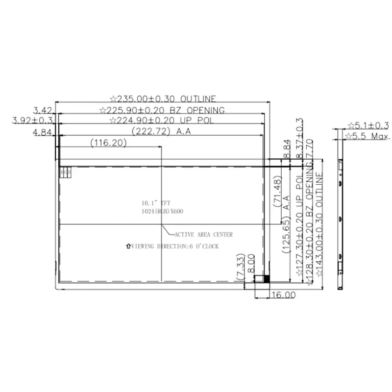
| Active area | 222.72 × 125.28 mm |
| Touch assembly | 252.00 × 155.50 × 6.85 mm |
| Display interface | LVDS |
| Connector | 40-pin FPC |
| Touch type | Capacitive |
| Luminance | 200 cd/m² typical; 180 cd/m² minimum |
| Display mode | Transmissive, normally white |
| Viewing direction | 6 o’clock |
| Backlight | 21-chip white LED |
| Display power reference | 0.85 W |
| Backlight power reference | 1.83 W maximum |
| Total power reference | 2.68 W maximum |
1024×600 Layout for Industrial Interfaces
The 1024 × 600 landscape format is suited to conventional HMI page structures.
Practical interface design
The screen can accommodate:
- Machine-state graphics
- Process values
- Alarm lists
- Control buttons
- Equipment settings
- Trend summaries
- Access-control prompts
- Building automation pages
- Test and service menus
- Compact POS operator interfaces
The 222.72 × 125.28 mm active area provides enough room for touch targets and readable text while remaining compact enough for equipment panels.
Processing requirement
A 1024 × 600 interface can reduce graphics and memory demands compared with higher-resolution 10.1-inch panels. The host still needs native timing and a compatible LVDS transmitter or controller board.
A matching resolution does not establish electrical compatibility.
Optical Performance for Controlled-Light Equipment
The standard configuration provides 200 cd/m² typical luminance, with 180 cd/m² identified as the minimum.
Suitable lighting conditions
This brightness level is primarily appropriate for:
- Indoor machine panels
- Equipment rooms
- Wall-mounted control interfaces
- Access terminals
- Commercial equipment
- Embedded monitors inside controlled environments
The standard configuration is not positioned as sunlight readable.
Touch-cover transmission, enclosure reflections and front printing can reduce perceived brightness. Test the final assembly under the actual operating light before production approval.
Normally-white optical mode
The transmissive, normally-white TFT structure and 6 o’clock viewing direction should be considered when defining the installed screen angle. The operator’s primary viewing position should be checked using a physical sample because no full directional angle sequence is confirmed.
LVDS and 40-Pin Host Qualification
The 40-pin FPC carries the display-related electrical connections, but pin count alone does not define compatibility.
Information required from the host
Confirm:
- Native 1024 × 600 timing
- LVDS channel configuration
- LVDS bit mapping
- Clock frequency
- Data polarity
- Logic-voltage domain
- Ground-pin positions
- Backlight pins
- Backlight enable
- PWM dimming input
- FPC pitch
- Contact side
- Cable orientation
A 40-pin connector does not guarantee compatibility with another 40-pin LVDS panel.
Controller-board requirement
A host without native LVDS output needs a suitable display controller or bridge. HDMI, MIPI DSI, RGB, eDP and USB video cannot connect directly to the panel’s native LVDS input without the correct conversion electronics.
10.1 Inch LVDS Touchscreen Panel Integration
Capacitive touch is included in the product configuration, but the touch interface must be confirmed independently of the LVDS image path.
Separate display and touch functions
LVDS carries display pixel data. It does not normally carry capacitive-touch coordinates.
The touch controller may require a separate control interface, interrupt line, reset line and power domain. The exact controller, voltage and communication method must be obtained from the approved touch-panel specification.
Touch qualification
Before PCB release, confirm:
- Touch-controller model
- Electrical interface
- Supply voltage
- Interrupt and reset signals
- FPC pin assignment
- Number of supported touch points
- Firmware or driver requirements
- Coordinate orientation
- Cover thickness
- Touch sensitivity
- Noise performance
- Grounding method
Do not assume I²C, USB or SPI until the ordered touch configuration is documented.
Mechanical Fit and Enclosure Design
The integrated touch assembly measures 252.00 × 155.50 × 6.85 mm.
Active area versus product outline
The visible image area is 222.72 × 125.28 mm. The remaining area accommodates the touch border, bonding structure and mechanical margin.
The enclosure design should define:
- Visible window
- Black-border coverage
- Touch-active region
- Assembly tolerance
- FPC exit
- Cable bend radius
- Rear clearance
- Mounting or bonding method
- Service-removal route
Use the complete touch-assembly drawing rather than the bare-LCD outline when releasing the front housing.
Touch-stack allowance
The 6.85 mm assembly depth is greater than the bare LCD thickness. Do not design the enclosure from an LCD-only drawing when capacitive touch is required.
Power and Backlight Planning
The available electrical references separate display and backlight power.
Power values
The documentation shows:
- Display power: 0.85 W
- Backlight power: 1.83 W maximum
- Combined power: 2.68 W maximum
- White LED backlight: 21 chips
- Backlight voltage reference: 23.1 V shown
These values require confirmation against the controlled production specification before selecting the final driver.
Backlight driver
The host system may need:
- Constant-current LED driver
- Backlight enable control
- PWM dimming
- Startup-current margin
- Thermal review
- Cable-voltage-drop review
Do not power the backlight directly from a logic-voltage rail without validating the approved LED circuit.
Temperature-Grade Qualification
Two temperature datasets appear for this product family.
One set shows operation from −20°C to +70°C and storage from −30°C to +80°C. Another set shows operation from 0°C to +50°C and storage from −10°C to +60°C.
The ordered temperature grade must be approved before publication, qualification testing or production release.
A temperature value taken from a different drawing revision should not be transferred automatically to this touch assembly.
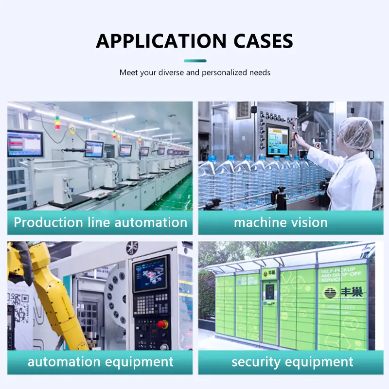
Recommended Applications
The panel can be evaluated for:
- Indoor industrial HMI
- Machine controls
- Automation panels
- Building-control interfaces
- Access terminals
- Smart-equipment controls
- Commercial equipment
- Portable test and service equipment
- Equipment dashboards
- Compact operator stations
- Project-qualified healthcare equipment interfaces
Suitability depends on host timing, touch interface, enclosure, lighting, temperature and power validation.
The product should not be described as waterproof, outdoor rated, automotive grade or medically certified without separate evidence.
Customization and Engineering Review
Project evaluation can cover:
- LVDS pin mapping
- FPC layout and orientation
- Touch-controller selection
- Cover structure
- Touch sensitivity
- Brightness target
- Backlight driver
- Mechanical adaptation
- Bonding method
- Packaging
- Branding
- Controller-board matching
Custom configurations are generally reviewed from 500 pieces, subject to tooling, material availability and the requested specification. Sample and standard-module quantities are confirmed separately.
Procurement Checklist
Confirm before approval:
- Native 1024 × 600 timing
- LVDS channel count
- LVDS bit mapping
- Complete 40-pin assignment
- Connector pitch and contact side
- FPC orientation
- Panel logic voltage
- Backlight voltage and current
- Backlight enable and PWM
- Touch-controller model
- Touch interface
- Touch voltage
- Interrupt and reset signals
- Touch-point requirement
- Firmware or driver requirement
- Active area: 222.72 × 125.28 mm
- Touch assembly: 252.00 × 155.50 × 6.85 mm
- Enclosure opening
- FPC bend clearance
- Mounting or bonding method
- 200 cd/m² lighting suitability
- 6 o’clock viewing fit
- Approved operating temperature
- Approved storage temperature
- Maximum power requirement
- Sample quantity
- Annual demand
- Production schedule
- Controller-board requirement
- Approved mechanical and electrical drawings
FAQ
About 10.1 Inch LVDS Touchscreen Panel
What must be checked before replacing another 40-pin LVDS panel?
Does the LVDS connection also carry capacitive-touch data?
Which temperature range should be used for qualification?
Is 200 cd/m² suitable behind a capacitive-touch cover?
What electrical information is needed for the backlight?
Which dimensions should control the enclosure design?
Freya Yang
+86 18318948097