Freya Yang
+86 18318948097
+852 62667476
10.1 Inch LVDS Capacitive Touch Screen Module for Industrial HMI

Model P/N
Size
Resolution
Brightness
Viewing Angle
Connector Type
Operating Temp
Overall(mm)
huisoar
HS101-02
Brand
Panel Size (inch)
Model P/N
Resolution
Brightness (nits)
Viewing Angle
Contrast Ratio
Response Time
Overall (mm)
Active Area (mm)
Refresh Rate
Display Colors
Panel Type
Connector Type
Surface Treatment
Operating Temp
Touchscreen Type
Storage Temp
Work Mode
Pixel Format
Control Type
Operating Environment
Designed For
10.1 Inch LVDS Capacitive Touch Screen Module for Industrial HMI
This 1024×600 TFT touch assembly combines a 40-pin LVDS display path with a capacitive front panel for indoor equipment interfaces.
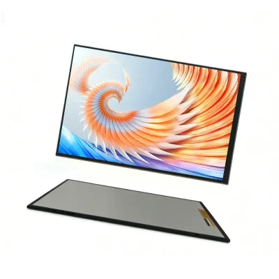
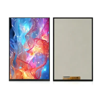
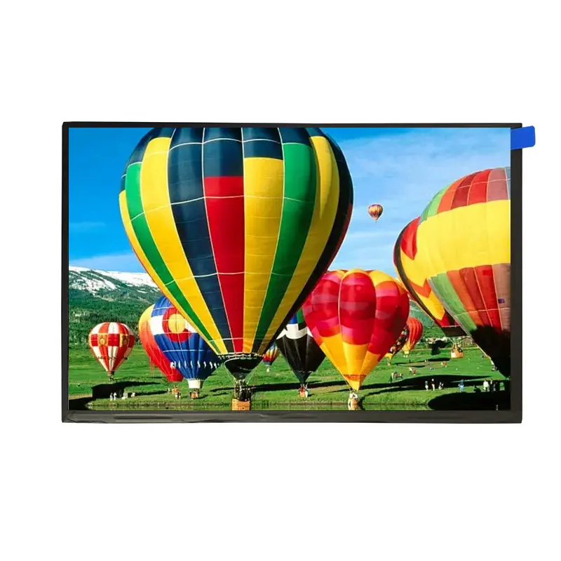
The LVDS Capacitive Touch Screen Module is a 10.1-inch landscape display assembly for industrial HMI, equipment controls, and other embedded interfaces that need direct touch operation. It combines a 1024×600 TFT LCD, capacitive touch panel, 40-pin LVDS connection, and a 222.72 × 125.28 mm active image area.
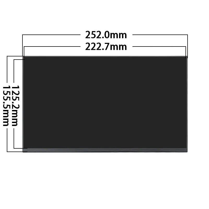
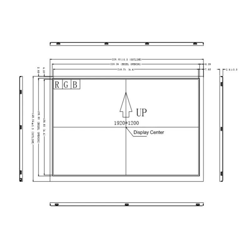
The complete touch assembly measures 252.00 × 155.50 × 6.85 mm. This is larger and thicker than many bare 10.1-inch LCD panels, so the touch outline—not the active area alone—must control enclosure design.
Key Specifications at a Glance
| Parameter | Value |
|---|---|
| Display size | 10.1 inch |
| Native resolution | 1024 × 600 pixels |
| Touch technology | Capacitive touch panel |
| Display interface | LVDS |
| Connector | 40-pin FPC |
| Active area | 222.72 × 125.28 mm |
| Touch-assembly outline | 252.00 × 155.50 × 6.85 mm |
| Display mode | Transmissive, normally white |
| Viewing direction | 6 o’clock |
| Luminance | 200 cd/m² typical; 180 cd/m² minimum |
| Uniformity | 75% typical; 70% minimum |
| Backlight | 21-LED white backlight |
| Upper polarizer | Frosted |
A 40-pin connector does not guarantee compatibility with another 40-pin LVDS display.
1024×600 Layout for Industrial Interfaces
The 1024×600 landscape format provides practical space for machine status, operating menus, trend graphs, alarm lists, settings, and on-screen controls. It supports a wider interface than portrait modules while avoiding the processing and memory requirements of higher-resolution panels.
Native-resolution UI design
The graphical interface should be designed around the native 1024×600 pixel grid. This helps preserve text clarity, icon proportions, and touch-target placement without relying on display scaling.
The UI plan should define:
- Native framebuffer resolution
- Landscape orientation
- Touch-target dimensions
- Menu and status-bar height
- Safe bezel margins
- Boot-screen orientation
- Font and icon scaling
- Alarm and warning visibility
Active area and front opening
The visible image area is 222.72 × 125.28 mm. The front opening should expose this area without pressing on the active glass or interfering with the touch border.
The finished bezel must also account for adhesive, touch-panel border, mechanical tolerances, and the 252.00 × 155.50 mm outer assembly.
40-Pin LVDS Interface Compatibility
LVDS is the display-data interface for this module. The interface name and pin count are not enough to approve a host connection.
Required electrical checks
Before applying power, verify:
- Native 1024×600 timing
- Single- or dual-channel LVDS arrangement
- LVDS bit mapping
- Pixel-clock requirements
- Complete 40-pin assignment
- Panel supply voltage
- Logic voltage
- Enable and reset signals
- Backlight-control signals
- Connector pitch
- Contact side
- FPC insertion direction
- Ground and shielding arrangement
Two LVDS modules with the same resolution may still use different mappings, voltages, timing, or cable orientation.
Non-LVDS hosts require conversion
HDMI, DisplayPort, eDP, MIPI DSI, parallel RGB, and USB video cannot be connected directly to the LCD’s native LVDS input. A suitable controller or bridge must generate the approved timing and electrical format.
The controller should be qualified with the exact module pinout rather than selected only by resolution.
Separate Display and Touch Paths
The display image travels through the LVDS connection. The capacitive-touch controller uses a separate control path unless the approved assembly documentation explicitly defines another architecture.
Touch information to confirm
The following touch details are not established by the 40-pin LCD connector:
- Touch-controller model
- I²C, USB, UART, or other interface
- Touch connector and pinout
- Logic voltage
- Interrupt signal
- Reset signal
- Touch-point count
- Firmware or driver requirements
- Coordinate orientation
- Cover-lens dimensions
The host board should reserve the correct touch signals only after the approved touch specification is available.
Coordinate and image alignment
Touch coordinates must align with the 1024×600 image orientation. A sample should be tested for:
- Correct X/Y direction
- Edge accuracy
- Rotation
- Touch-to-pixel alignment
- Dead-zone behavior
- Bezel interference
- Enclosure pressure
- Cable routing
Capacitive touch is confirmed, but multi-touch capability is not claimed without the controller specification.
Optical Performance and Lighting Environment
The LCD is specified at 200 cd/m² typical and 180 cd/m² minimum luminance.
Indoor-use brightness boundary
The 200 cd/m² configuration is intended primarily for indoor or controlled-light equipment.
It can suit enclosed machinery, control cabinets, building-control interfaces, and operator stations where direct sunlight is not expected. It should not be described as sunlight readable or outdoor readable.
The touch stack and cover treatment may reduce the luminance perceived by the operator. Final readability should therefore be evaluated with the finished touch assembly and enclosure.
Display mode and viewing direction
The TFT operates in transmissive, normally-white mode and has a 6-o’clock viewing direction. This means installation orientation affects how the image appears from different operator positions.
A sample should be evaluated at the intended mounting height and operator angle before the enclosure is finalized.
Surface treatment
The upper polarizer is frosted, while the lower polarizer is described as smooth. The frosted upper surface may help manage direct reflections in indoor equipment, but no quantified haze, gloss, or anti-glare grade is confirmed.
Mechanical Integration of the LVDS Capacitive Touch Screen Module
The complete assembly measures 252.00 × 155.50 × 6.85 mm. This value should control initial enclosure planning for the touch version.
Touch assembly versus bare LCD
Do not substitute the dimensions of a standard 235 × 143 mm bare LCD when releasing a bezel for this configuration. The wider touch assembly changes:
- Outer width and height
- Front-panel opening
- Total depth
- FPC clearance
- Adhesive area
- Support zones
- Cable routing
- Bezel overlap
Structural support
The display should be supported around approved perimeter areas rather than loaded through the active image region. Allow clearance for the LCD and touch FPCs and maintain a suitable bend radius.
The rear frame is described as a 0.25 mm aluminum-zinc plate. Enclosure design should avoid concentrated pressure or twisting that could stress the glass or rear structure.
Backlight and Power Qualification
The backlight is described as a 21-LED white-light structure. The electrical note gives a forward-voltage reference of 23.1 V and 25 mA per LED.
These values should be treated as backlight electrical references, not as a complete backlight-driver specification.
Backlight-driver checks
Confirm:
- String topology
- Number of strings
- Current regulation
- Maximum and typical voltage
- Enable polarity
- Dimming method
- Startup behavior
- Thermal limits
- Connector assignment
The source also presents numerical panel, backlight, and total power values without an explicit unit. Those values should not be used in the public power budget until the approved electrical specification confirms the unit and test conditions.
Temperature Specification Requires Revision Confirmation
Two different temperature sets are associated with the product information:
- −20°C to +70°C operation and −30°C to +80°C storage
- 0°C to +50°C operation and −10°C to +60°C storage
These ranges cannot be merged or selectively upgraded.
The approved module revision, production drawing, and supplier confirmation must establish the temperature limits used for product qualification. Until then, the application should not be marketed as wide-temperature or industrial-temperature grade.
Recommended Applications
The module may be considered for:
- Machine operator panels
- Indoor industrial HMI
- Equipment dashboards
- Building-control interfaces
- Smart-appliance controls
- Compact POS operator interfaces
- Access-control terminals
- Indoor diagnostic equipment
- Portable test and service equipment
- Commercial information terminals
Final application approval depends on host compatibility, lighting, viewing orientation, enclosure design, touch performance, backlight driving, and the approved temperature range.
Customization and Project Review
Project-specific review may cover:
- Touch-controller and interface selection
- Cover-lens dimensions
- Touch-panel outline
- Touch FPC routing
- LVDS pin definition
- Display FPC shape and length
- Brightness target
- Backlight electrical requirements
- Surface treatment
- Bezel and mounting geometry
- Controller-board matching
- Cable set
- Packaging and documentation
Custom configurations are generally reviewed from 1,000 pieces, subject to tooling requirements, material availability, and the requested specification. Samples and standard-module quantities are confirmed separately.
Procurement and Sample Approval Checklist
Confirm these items before PCB, cable, bezel, or mold release:
- Native 1024×600 timing
- LVDS channel configuration
- LVDS mapping and bit width
- Complete 40-pin assignment
- Panel voltage
- Backlight topology
- Backlight-driver limits
- FPC pitch
- FPC contact side
- Cable orientation
- Touch-controller model
- Touch interface and pinout
- Touch logic voltage
- Touch-point requirement
- Coordinate orientation
- Active area
- Touch-assembly outline
- Total thickness
- Bezel opening
- 200 cd/m² lighting suitability
- 6-o’clock viewing orientation
- Final operating-temperature range
- Final storage-temperature range
- Sample quantity
- Annual demand
- Production schedule
- Controller or bridge requirement
FAQ
About LVDS Capacitive Touch Screen Module
What must be checked before replacing another 40-pin LVDS panel?
Is touch control carried through the LVDS display connection?
Is 200 cd/m² sufficient behind the touch panel?
Which temperature range should be used for qualification?
Which dimensions should control enclosure release?
Freya Yang
+86 18318948097