~
~
~
~
~
~
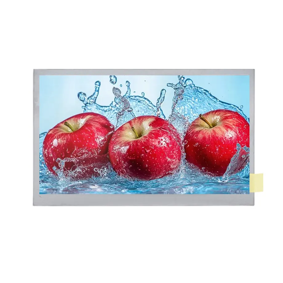
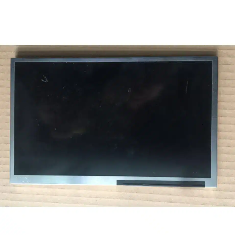
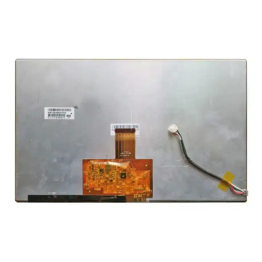
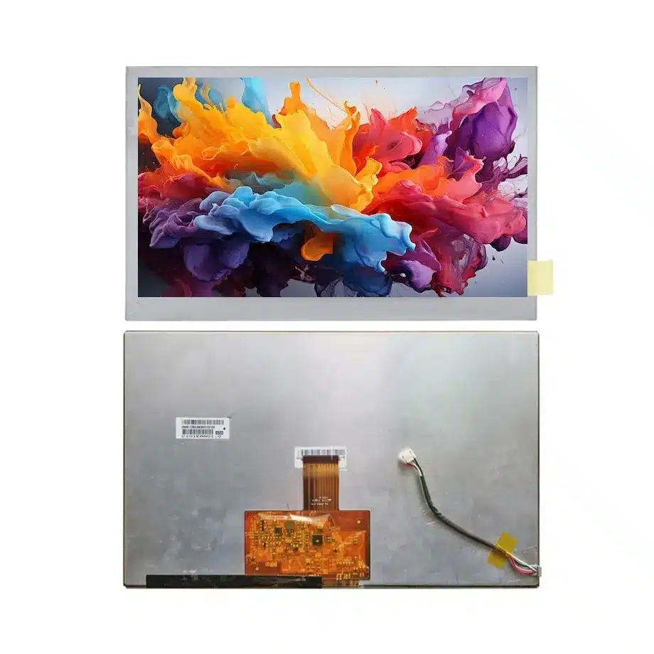
C101EAN07.0 Wide-Temperature SPI LCD Cell AUO
Model P/N
Size
Resolution
Brightness
Viewing Angle
Connector Type
Operating Temp
Overall(mm)
auo
C101EAN07.0
Brand
Panel Size (inch)
Model P/N
Resolution
Viewing Angle
Contrast Ratio
Response Time
Overall (mm)
Active Area (mm)
Refresh Rate
Display Colors
Panel Type
Connector Type
Surface Treatment
Operating Temp
Touchscreen Type
Storage Temp
Work Mode
Pixel Format
Input Voltage (V)
Designed For
Product Details
Product Overview
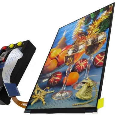
C101EAN07.0 Wide-Temperature SPI LCD Cell is a 10.1-inch AUO a-Si TFT-LCD FOG cell for automotive display integration. The cell uses a native 1280(RGB)×720 WXGA raster in a 16:9 format, with a 223.68 × 125.82 mm active area inside a 232.28 × 139.42 × 1.08 mm outline. The IPS normally-black transmissive structure is specified at 1000:1 typical contrast, 80/80/80/80 typical viewing-angle values at CR≥10 and 16.7M colors. The front-surface specification lists 6.5% maximum reflection, while the exact-model feature set also includes sRGB wording and up/down plus left/right reverse capability.
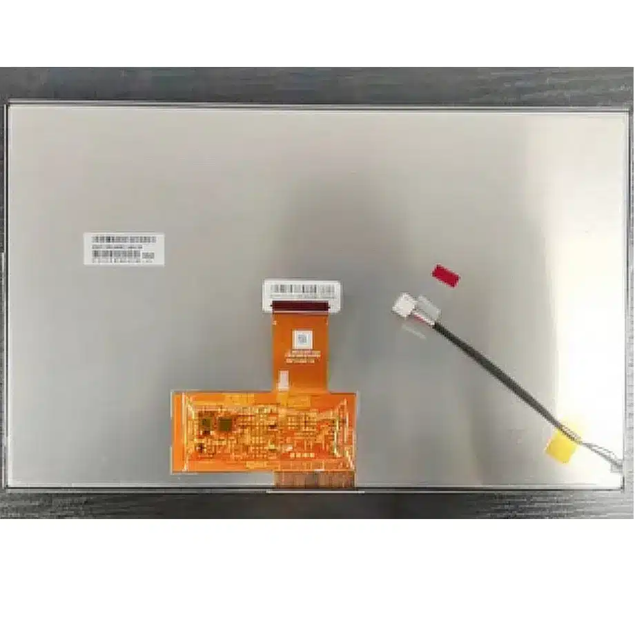
This is a cell without a backlight or touch screen, so the 0 cd/m² luminance entry is not a finished-display brightness target. The system must provide the illumination, optical films, cover stack and mechanical structure. Native signaling combines single-channel 8-bit LVDS with SPI on a 40-pin 0.5 mm FPC. The panel uses 3.3 V VDD and 3.3 V VDDA typical rails, runs at 60 Hz and is specified for -30 to 85 °C operation and -40 to 95 °C storage. The response field gives 20/20 maximum Tr/Td; because these are time quantities, they are represented as 20/20 ms without changing the numeric values.
Three Core Buyer Value Propositions
1. LVDS plus SPI separates pixel transport from panel-control functions
The interface definition is more specific than a generic automotive LVDS label. The image path uses one 8-bit LVDS channel, while SPI provides an additional control path. That separation helps the controller-board team identify both high-speed video requirements and lower-speed configuration needs before schematic release. Exact pin mapping, SPI register behavior, timing and power sequence remain model-specific and should come from the controlled AUO documentation.
2. A bare cell gives the integrator control over brightness, backlight and front-surface optics
Because the cell contains no backlight, the system designer can select the LED source, light guide, diffuser films and dimming architecture to meet the vehicle program. The same freedom means the finished optical result cannot be inferred from the 0 cd/m² cell entry. Backlight luminance, cover reflection, optical bonding, thermal performance and night-dimming behavior all need to be engineered and measured at the assembled display level.
3. Wide temperature limits and reverse-display capability fit disciplined vehicle-display validation
The -30 to 85 °C operating range, -40 to 95 °C storage range and reverse-display feature wording provide useful inputs for automotive integration planning. They do not establish a named OEM qualification, AEC compliance or functional-safety status. The buyer should translate those component limits into a system test plan that includes controller electronics, backlight, FPC, cover lens, bonding and enclosure under the intended cabin environment.
Key Specifications at a Glance
| Parameter | Confirmed value |
|---|---|
| Manufacturer / model | AUO C101EAN07.0 |
| Display size | 10.1 inch |
| Panel form | a-Si TFT-LCD, CELL (FOG), no backlight |
| Native resolution | 1280(RGB)×720 WXGA, 16:9 |
| Active area | 223.68 × 125.82 mm |
| Outline | 232.28 × 139.42 × 1.08 mm |
| Display mode | IPS, Normally Black, Transmissive |
| Contrast ratio | 1000:1 typical |
| Viewing-angle values | 80/80/80/80 typical at CR≥10 |
| Response time | 20 / 20 ms maximum Tr / Td |
| Colors | 16.7M |
| Surface | Reflection 6.5% maximum |
| Refresh rate | 60 Hz |
| Native interface | LVDS, 1 channel, 8-bit + SPI |
| Connector | 40-pin 0.5 mm FPC |
| Panel input | 3.3 / 3.3 V typical, VDD / VDDA |
| Touch | Without touch screen |
| Operating / storage | -30 to 85 °C / -40 to 95 °C |
How should the LVDS and SPI paths be divided in the controller design?
Texas Instruments' LVDS engineering material explains the electrical fundamentals of differential signaling, while the C101EAN07.0 implementation adds a separate SPI control path. For this cell, the LVDS channel carries the display data and timing; SPI should be treated as a model-specific control interface whose commands and sequencing must be verified against the AUO specification.
During bring-up, verify 1280×720 at 60 Hz, color-bit mapping, LVDS clocking, SPI initialization, reset behavior and repeated power cycling. If a remote serializer/deserializer architecture is used elsewhere in the vehicle, keep that link conceptually separate from the cell-native LVDS interface. A bridge or SerDes device may change the wiring topology but does not alter the panel's own pinout or timing requirements.
External backlight design and the meaning of 0 cd/m²
C101EAN07.0 Wide-Temperature SPI LCD Cell is delivered as a FOG cell without an integrated light source. The listed 0 cd/m² therefore reflects the cell-only configuration rather than a black-screen performance target. Finished luminance depends on the backlight, optical films, polarizer losses, aperture and cover stack. The display integrator should define day, dusk and night luminance targets and then size the backlight to those system-level requirements.
Backlight qualification should include current regulation, dimming depth, thermal rise, color temperature and brightness stability across temperature. If the vehicle program requires sunlight readability, high ambient contrast or automatic dimming, those requirements need their own optical and control evidence. The bare cell's 1000:1 typical transmissive contrast is one input to that design, not a complete in-cabin contrast specification.
Surface reflection and sRGB wording require careful interpretation
The exact surface entry gives 6.5% maximum reflection. That is useful for optical-stack planning because front reflections can strongly influence apparent black level in a bright cabin. Adding cover glass, anti-reflection treatment or optical bonding can change the final result, so measure the complete assembly rather than assuming the cell value transfers directly through additional layers.
The exact-model feature list includes sRGB wording, but the provided color field does not establish a numerical sRGB coverage percentage or factory calibration target. Do not convert that feature phrase into “100% sRGB” or a color-accuracy promise. If a cockpit program controls white point, gamma or color matching across multiple displays, define those acceptance metrics separately and validate production samples.
Mechanical integration of a 1.08 mm automotive cell
The 232.28 × 139.42 × 1.08 mm outline is a cell-level envelope and excludes a finished backlight and structural frame. The 223.68 × 125.82 mm active area should be checked against the visible aperture separately from the outer glass. Housing support should avoid point loading, edge stress and FPC strain while preserving thermal expansion clearance across the -30 to 85 °C operating range.
Replacement approval should compare the exact cell outline, FPC position, 40-pin connector geometry and image orientation. A 10.1-inch 1280×720 panel can look equivalent on a specification summary while using different signaling, polarizer orientation or mechanical datums. Full-suffix control is particularly important when the display is assembled into a custom vehicle backlight and cover system.
Reverse display functions and image-orientation validation
The model's feature list identifies up/down and left/right reverse capability. These functions can be useful when a controller or mechanical layout requires alternate scan orientation, but they should be verified in the production initialization sequence. A reverse-display setting is a logical image function; it is not permission to flip a connector or FPC mechanically.
Qualification should include normal and any required reversed modes after cold start, warm restart and sleep or ignition-cycle transitions. If diagnostic firmware uses a different initialization path from normal operation, test that path as well. Documenting orientation behavior helps prevent a replacement controller or firmware update from producing a mirrored or inverted image in the field.
Wide-temperature operation without overstating qualification
AUO's automotive display overview shows dashboard, center-console, mirror and rear-seat display applications across its broader automotive portfolio. C101EAN07.0 itself is documented for Automotive Display use and carries the stated -30 to 85 °C operating range. Those facts support vehicle-display engineering, but they do not identify a specific cockpit location or certify the finished system for an OEM.
Temperature testing should include the external backlight, controller, SPI behavior, FPC, bonding and enclosure because each subsystem can introduce its own limits. At cold temperature, evaluate startup and liquid-crystal response; at high temperature, evaluate image stability, optical shift and thermal margin. Storage testing should also consider adhesives and mechanical stress over the -40 to 95 °C range.
Response time and 60 Hz system performance
The documented rise and decay values are 20 ms maximum each. These are panel transition limits, not an end-to-end camera, HMI or navigation latency specification. At 60 Hz, graphics processing, buffering, SerDes transport if present and software rendering add separate delays. The complete vehicle display should therefore be evaluated with representative video and HMI transitions on production-intent electronics.
Do not replace the 20/20 ms Tr/Td pair with a single gray-to-gray figure from another AUO panel. Measurement methods differ, and a seemingly faster number may not be comparable. Preserving the exact qualifier is more useful for engineering than compressing unlike response metrics into one marketing value.
Application fit for vehicle display-cell programs
C101EAN07.0 Wide-Temperature SPI LCD Cell is documented for Automotive Display use. It is best suited to a vehicle display assembly intentionally designed around a 10.1-inch WXGA IPS cell, LVDS plus SPI control, external illumination and the exact 40-pin FPC. That can support instrument, information or entertainment display development only after the complete assembly is qualified for the target location. No named vehicle, dashboard, CID or cluster fit is asserted from the cell specification alone.
The cell has no integrated touch function. If touch is required, the sensor, controller, cover and bonding stack must be qualified separately, including their influence on reflection and thickness. For sourcing, lock the exact C101EAN07.0 suffix and current revision rather than accepting another C101-series part solely because the visible resolution matches.
Procurement and validation checklist
- Lock AUO C101EAN07.0 and its approved revision in the product BOM.
- Validate native 1280×720 timing at 60 Hz over single-channel 8-bit LVDS.
- Verify the SPI control sequence, reset behavior and exact 40-pin 0.5 mm FPC mapping.
- Design the external backlight for the required finished luminance and dimming range.
- Check the 232.28 × 139.42 × 1.08 mm cell outline and FPC location against the mechanical stack.
- Evaluate the 6.5% maximum cell reflection within the complete cover and bonding design.
- Test operation from -30 to 85 °C and storage effects across -40 to 95 °C.
- Preserve the 20/20 ms maximum Tr/Td response definition during substitute comparisons.
- Qualify any added touch solution independently because the exact cell is non-touch.
For C101EAN07.0 Wide-Temperature SPI LCD Cell qualification, provide the controller and SPI architecture, LVDS timing, FPC drawing, backlight design, optical stack, vehicle environmental targets and required quantity. The cell should be released only when its electrical, optical and mechanical requirements are proven in the intended automotive display assembly.
Recommended: Same Size
(10.1")
Applications & Value of LCD Panel

- Fast sourcing with in-stock panels & cross-reference alternatives
- Stable supply chain with long-term availability
- Engineering-level support from panel to integration
- Custom solutions: cable, touch & optical bonding
- Strict quality control with IQC / OQC / aging test
- Full traceability system for quality assurance
- Complete technical documentation & drawings
- Compliance support: RoHS & certification files