Freya Yang
+86 18318948097
+852 62667476
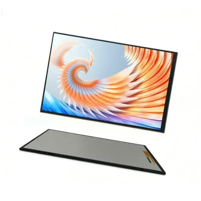
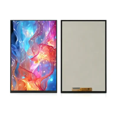
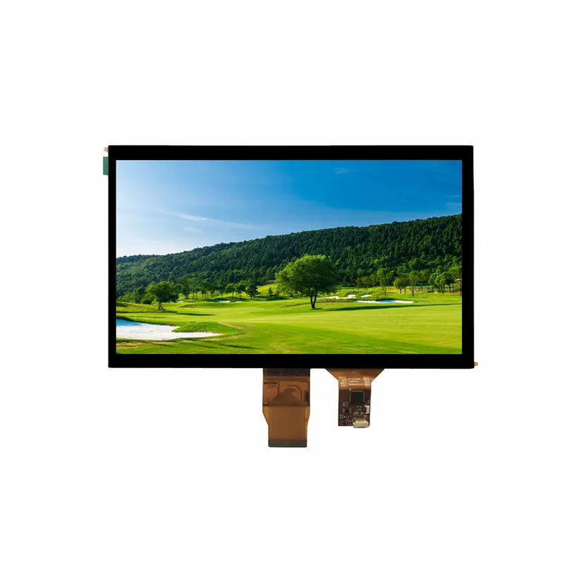
10.1 Inch Equipment Interface RGB Display Module for Control Panels
Model P/N
Size
Resolution
Brightness
Viewing Angle
Connector Type
Operating Temp
Overall(mm)
huisoar
HS101225A07LM
Brand
Panel Size (inch)
Model P/N
Resolution
Brightness (nits)
Viewing Angle
Contrast Ratio
Response Time
Overall (mm)
Active Area (mm)
Refresh Rate
Bezel Opening
Display Colors
Panel Type
Connector Type
Surface Treatment
Operating Temp
Touchscreen Type
Storage Temp
Work Mode
Pixel Format
Input Voltage (V)
Operating Environment
Designed For
10.1 Inch Equipment Interface RGB Display Module for Control Panels
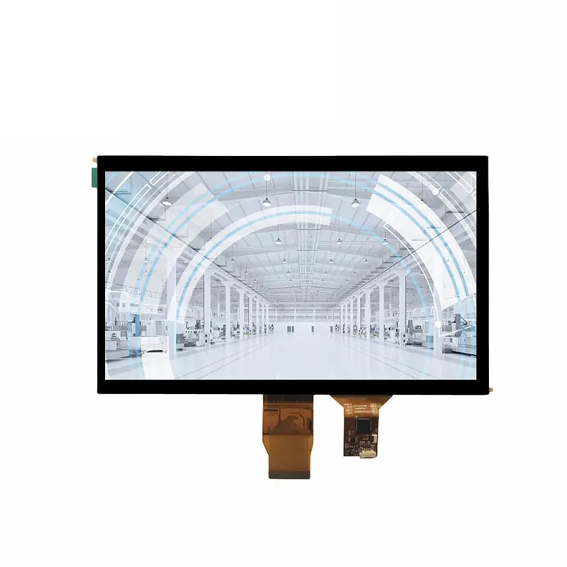
A 10.1-inch 1024 × 600 normally white TFT module uses an RGB interface, 500 cd/m² luminance and a 12 o’clock preferred viewing direction for embedded control interfaces.
The Equipment Interface RGB Display Module provides a 222.72 × 125.28 mm image area for status pages, menus, equipment data and graphical controls. Its a-Si TFT active-matrix construction is transmissive and normally white, with an anti-glare surface, 16.7M colors and a 24-LED backlight. Touch is optional rather than included, so display and touch requirements should be qualified separately.
Product Summary
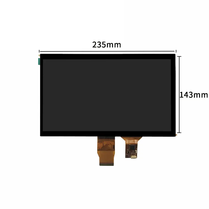
The 1024 × 600 pixel format gives embedded developers room for multi-zone layouts without moving to a larger enclosure. The 235.0 × 143.0 × 6.0 mm outline supports landscape equipment panels, while the 0.2175 × 0.2088 mm pixel pitch defines the native image geometry.
Native 1024 × 600 Content
Prepare the interface at the native raster to avoid unnecessary scaling. Text, icons, alarms and control targets should be checked at the intended viewing distance, especially when a protective window or touch layer is added.
Normally White Transmissive Operation
The module is listed as normally white and transmissive. Final contrast and grayscale behavior should be checked with the intended controller timing, mounting orientation and ambient light.
Key Specifications
| Parameter | Specification |
|---|---|
| Display size | 10.1 inch |
| Resolution | 1024 × 600 pixels |
| Display technology | a-Si TFT active matrix |
| Display mode | Normally white, transmissive |
| Pixel configuration | RGB vertical stripe |
| Pixel pitch | 0.2175(H) × 0.2088(V) mm |
| Active area | 222.72(W) × 125.28(H) mm |
| Module outline | 235.0(W) × 143.0(H) × 6.0(D) mm |
| Interface | RGB |
| Brightness | 500 cd/m² |
| Surface treatment | Anti-glare |
| Preferred viewing direction | 12 o’clock |
| Display colors | 16.7M |
| Backlight | 24 LEDs |
| Touch | Optional; technology and interface require confirmation |
| Operating temperature | −20°C to +70°C |
| Storage temperature | −30°C to +80°C |
Optical and Viewing-Direction Planning
Evaluate 500 cd/m² in the Finished Stack
The 500 cd/m² luminance is suitable for many indoor industrial and commercial interfaces, but it does not establish sunlight readability. Window transmission, reflections, air gaps, touch overlays, installation angle and enclosure temperature can reduce apparent contrast. Test the complete assembly under the intended lighting.
Use the 12 O’Clock Direction in Mechanical Planning
A 12 o’clock viewing direction means the display is optimized for observation from above the panel centerline. This can suit a screen mounted below the operator’s eye level, but the cabinet angle and user position should be confirmed with a sample. Off-direction viewing may change contrast, grayscale or color appearance.
Equipment Interface RGB Display Module Integration
RGB Timing and Pin Assignment Must Match
The RGB interface designation does not identify the complete electrical implementation. Confirm the approved connector drawing, pin count, pixel-clock range, synchronization method, data-enable behavior, voltage levels, RGB data width, signal polarity, FPC contact side and cable orientation.
A matching resolution or the word RGB does not guarantee direct compatibility with another module.
Separate Display Signals from Backlight Power
The 24-LED count does not define backlight voltage, current, enable, dimming or driver requirements. Obtain the approved electrical specification before designing the power stage. Treat the display-logic rail and backlight circuit as separate qualification items.
Controller Conversion May Be Required
HDMI, eDP, LVDS, MIPI DSI, USB video and other non-RGB hosts require a suitable bridge or controller. Confirm that it can generate native 1024 × 600 timing and the required RGB electrical format.
Mechanical Fit and Optional Touch
Active Area Versus Complete Outline
The 222.72 × 125.28 mm active area controls the visible opening and content alignment. The 235.0 × 143.0 × 6.0 mm outline controls enclosure clearance. Mounting tolerances, FPC routing, connector projection and keep-out zones require the approved drawing.
Touch Is an Optional Configuration
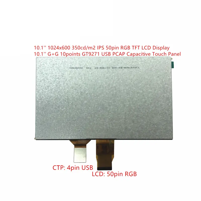
The product identifies a touch panel as optional without confirming capacitive or resistive technology, controller, interface, point count, cover size or bonding method. A touch-enabled build needs a separate drawing, part number and electrical definition.
Adding touch can change thickness, optical transmission, window dimensions, grounding and cable routing.
Temperature and Installation Boundaries
The module operates from −20°C to +70°C and stores from −30°C to +80°C. These component limits do not establish an IP rating, condensation resistance, vibration grade, UV resistance or finished-equipment certification.
Thermal testing should use the final enclosure, backlight operating point and airflow. Check cold start, image stability, luminance and FPC flexibility at the required limits.
Recommended Applications
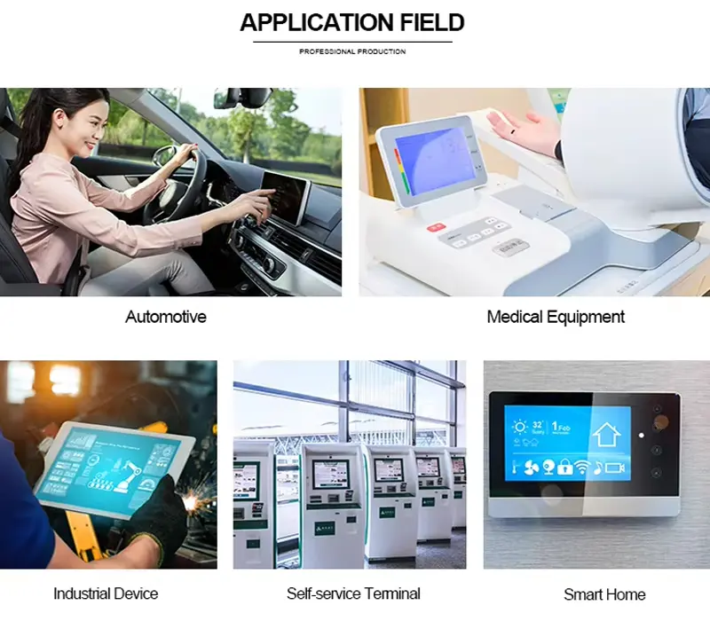
The Equipment Interface RGB Display Module can be evaluated for embedded control panels, equipment HMIs, smart-home controllers, industrial terminals, POS operator interfaces, self-service menu panels and test or service equipment.
Control and Monitoring Interfaces
The 1024 × 600 workspace supports status indicators, parameter pages, trend graphics, alarms and guided setup screens. Its wide active area helps keep several information zones visible.
Public and Commercial Operator Panels
The anti-glare surface and 500 cd/m² luminance can support indoor kiosks and operator-facing terminals after window testing. The module is not a complete monitor and does not include a confirmed media controller, touch controller, enclosure or external video input.
Customization and Sample Qualification
A modified Equipment Interface RGB Display Module project may include touch integration, cover-lens design, FPC or connector review, brightness adjustment, controller-board matching, branding or packaging. Custom configurations are generally reviewed from 500 pieces, subject to tooling requirements, material availability and the requested specification. Sample and standard-module quantities are confirmed separately.
The qualification sample should use the intended host, RGB cable or FPC, backlight driver, window, enclosure and installation angle. Approve image timing, color mapping, viewing direction, luminance, temperature operation, fit and any ordered touch function.
Procurement Checklist
- Confirm the assigned product revision and approved production datasheet.
- Submit native 1024 × 600 timing and required refresh rate.
- Confirm the complete RGB pin assignment, data width, voltage levels and signal polarity.
- Confirm connector pitch, contact side, FPC orientation and cable design.
- Obtain panel and backlight voltage, current, enable, dimming and power-sequence requirements.
- Approve the 222.72 × 125.28 mm active area.
- Approve the 235.0 × 143.0 × 6.0 mm module outline.
- Confirm the 12 o’clock direction against the operator eye line.
- Define window transmission, reflection and anti-glare requirements.
- Confirm no-touch use or specify the optional touch technology, interface and bonding.
- Define temperature, humidity, vibration, sealing and compliance requirements.
- Provide sample quantity, annual demand, schedule and acceptance criteria.
FAQ
About 10.1 Inch Equipment Interface RGB Display Module
What must be checked before connecting an existing RGB controller?
How should the 12 o’clock viewing direction affect installation?
Is a touchscreen included with the standard module?
Is 500 cd/m² sufficient behind a protective window?
Which dimensions should control the enclosure design?
Freya Yang
+86 18318948097