Freya Yang
+86 18318948097
+852 62667476
2.8 Inch Round TFT Screen for Smart Watch Prototypes
Model P/N
Size
Resolution
Brightness
Viewing Angle
Connector Type
Operating Temp
Overall(mm)
huisoar
HS028SV67A-V1
Brand
Panel Size (inch)
Model P/N
Resolution
Brightness (nits)
Viewing Angle
Contrast Ratio
Response Time
Overall (mm)
Active Area (mm)
Refresh Rate
Display Colors
Panel Type
Connector Type
Operating Temp
Touchscreen Type
Storage Temp
Work Mode
Pixel Format
Input Voltage (V)
Operating Environment
Designed For
2.8 Inch Round TFT Screen for Smart Watch Prototypes
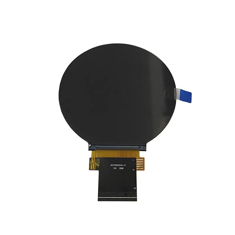
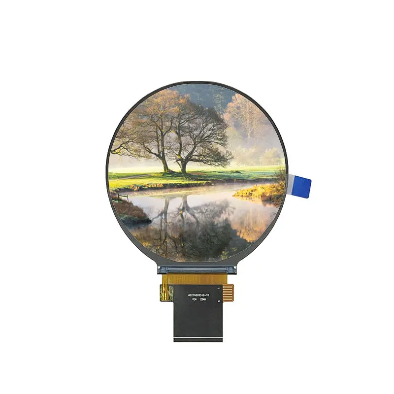
A circular 480 × 480 transmissive module with SPI-3W-RGB18 signaling, all-o’clock viewing and a 40-pin FPC for compact wearable prototypes.
Product Summary
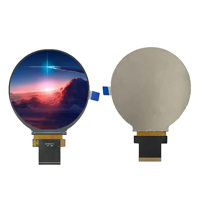
The Round TFT Screen for Smart Watch is a 2.8-inch circular display component for larger watch-style devices, wearable control interfaces and compact round HMIs. Its native 480 × 480 pixel format provides a balanced square raster that can be mapped into a circular visual area for dials, status rings, menus, notifications and instrument-style graphics.
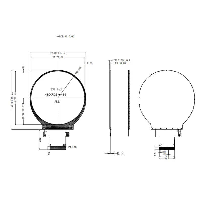
The display uses a transmissive TFT structure with an LED backlight. Its 70.13 × 70.13 mm active area is housed within a 73.00 × 77.59 × 2.30 mm module outline. Before selecting it for a wrist-worn product, the complete enclosure diameter, connector location, FPC bend and battery space must be reviewed.
Key Specifications
| Parameter | Confirmed value |
|---|---|
| Display size | 2.8 inches |
| Resolution | 480 × 480 pixels |
| LCD type | TFT / transmissive |
| Viewing direction | All O’Clock |
| Active area | 70.13 × 70.13 mm |
| Module outline | 73.00 × 77.59 × 2.30 mm |
| Pixel pitch | 0.1461 × 0.1462 mm |
| Interface | SPI-3W-RGB18 |
| Connector | 40-pin FPC |
| Driver IC | ST7701S |
| Listed input voltage | 2.8–3.3 V |
| Backlight | LED |
| Operating temperature | −20°C to +70°C |
| Storage temperature | −30°C to +80°C |
| Touch | Not confirmed |
Circular 480 × 480 UI Planning
Use the Native Square Raster Inside the Round View
The controller should output the native 480 × 480 raster. UI designers can then place critical information inside a circular safe area while using the corner pixels only when the mechanical mask leaves them visible.
Circular menus, progress rings and gauge graphics should be centered against the confirmed active-area drawing. Text, battery indicators and notification icons need sufficient margin from the curved edge so they remain readable after the cover lens and enclosure opening are applied.
Check the Watch-Case Envelope Before Tooling
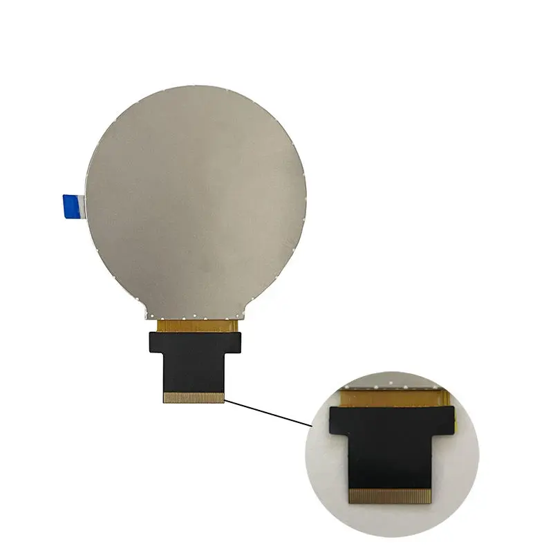
The screen is 2.8 inches diagonally, but the complete module measures 73.00 × 77.59 mm. That envelope is appropriate for larger watch-style prototypes and wrist-mounted controls only when the product housing can accommodate the panel, FPC, battery, PCB and mechanical support.
Do not approve tooling from the diagonal size alone. Use the full drawing, including the bottom flex position and required service clearance.
SPI-3W-RGB18 Integration for the Round TFT Screen for Smart Watch
Separate Serial Control from RGB Pixel Signals
The 40-pin drawing identifies SDA, SCK and CS serial-control signals together with PCLK, DE, VS, HS and DB0–DB17 RGB signals. The host design therefore needs an approved definition of how the three-wire serial path and RGB18 path are used.
A controller that supports a different SPI screen or another RGB panel is not automatically compatible. Confirm the pixel clock, synchronization mode, data mapping, polarity, blanking requirements and control-command sequence.
Verify the Complete 40-Pin Definition
The connector includes LED anode and cathode pins, grounds, VCC, reset, serial control, RGB timing, 18 data lines and touch-related labels. Pin count alone cannot establish compatibility with another 40-pin module.
Before PCB release, verify:
- Pin sequence and connector orientation
- FPC contact side and mating connector
- Logic-level limits
- RGB18 data order
- Clock and synchronization polarity
- Reset behavior
- Backlight connections
- Touch-related pin use
ST7701S and Power Qualification
Treat the Driver IC as a Documentation Reference
ST7701S identifies the display-driver family, but the part number does not replace the approved command, timing and power documentation. Firmware should be based on the exact panel revision rather than a generic initialization sequence copied from another ST7701S display.
Request the command package, reset requirements, sleep and wake behavior, timing table and power-on or power-off guidance for the ordered module.
Confirm the Scope of the 2.8–3.3 V Listing
The product information lists an input range of 2.8–3.3 V, while the connector separately provides LED A/K backlight pins. The listed voltage must not be assumed to cover the LED backlight.
Engineering review should separate:
- Panel logic supply
- I/O logic level
- Internal analog requirements
- Backlight voltage and current
- Enable or dimming control
- Startup and shutdown sequencing
Optical and Environmental Limits
Use All-O’Clock as Viewing-Direction Wording
The confirmed wording is All O’Clock viewing direction. That supports multi-orientation evaluation but does not independently establish IPS technology or a numerical viewing-angle grade.
The finished product must still be tested through its cover lens, printed border and selected mounting angle.
Qualify Luminance and Backlight Electrical Data
No standard luminance, contrast ratio or backlight electrical rating is confirmed. The module should therefore be treated as an optical configuration requiring sample measurement rather than being marketed as high brightness or outdoor readable.
Confirm luminance, uniformity, contrast, backlight current, thermal behavior and cover-lens reflection under the intended lighting conditions.
The listed environmental limits are −20°C to +70°C for operation and −30°C to +80°C for storage. Those component limits do not establish waterproof, drop, vibration or finished-wearable qualification.
Mechanical Fit and Touch Boundary
Design Around the 73.00 × 77.59 × 2.30 mm Outline
Mechanical support should avoid concentrated pressure on the circular glass. The enclosure must provide controlled seating, FPC clearance and a safe bend path without folding the flex sharply at the module edge.
The 70.13 × 70.13 mm active area should be aligned with the cover opening before the decorative border is finalized.
Touch-Labeled Pins Do Not Confirm an Installed Sensor
Pins labeled TPINT, TPSDA, TPSCL, TPRST and TPVCC appear in the connector definition. These labels indicate that the connector design provides a potential touch-signal path; they do not prove that a touch sensor, controller or cover lens is included in the standard module.
A touch configuration must specify the sensor structure, controller, communications protocol, operating voltage, cover-glass stack and combined outline.
Applications and Selection Boundaries
The Round TFT Screen for Smart Watch can be evaluated for:
- Larger smart-watch prototypes
- Wrist-mounted control devices
- Wearable instrument interfaces
- Circular status displays
- Smart-device rotary controls
- Compact round embedded HMIs
- Instrument and meter dials
Conventional compact watches require especially careful form-factor review because the 73.00 × 77.59 mm module envelope may control the complete product dimensions.
Configuration and Customization
Logo, packaging and graphic customization are listed from 500 pieces. Technical changes involving the FPC, pin mapping, touch system, cover lens, brightness, backlight, bonding or mechanical dimensions require a separate engineering and quantity review.
Samples and standard-module quantities are confirmed independently from customization quantities.
Procurement Checklist
Confirm:
- Assigned and supplier model revisions
- Native 480 × 480 timing
- Circular visible area and UI safe zone
- Complete 40-pin assignment
- FPC contact side, pitch and connector
- RGB18 data order
- Pixel-clock frequency and polarity
- HS, VS and DE requirements
- Three-wire SPI command path
- ST7701S command package
- Reset, sleep and wake behavior
- Panel and I/O voltage requirements
- Exact scope of the listed 2.8–3.3 V range
- LED-backlight voltage and current
- Luminance and contrast target
- 70.13 × 70.13 mm active-area position
- 73.00 × 77.59 × 2.30 mm enclosure fit
- FPC bend and strain relief
- Touch-panel requirement
- Touch controller and interface
- Cover-lens structure
- Operating and storage limits
- Sample quantity and acceptance criteria
- Annual demand and production schedule
FAQ
About 2.8 Inch Round TFT Screen
What must be checked before connecting the 40-pin interface?
Can the display be driven as an SPI-only screen?
Is 2.8 inches suitable for a conventional smartwatch?
Does the standard module include touch?
What documentation is required before approving a sample?
Freya Yang
+86 18318948097