Freya Yang
+86 18318948097
+852 62667476
7 Inch Operator Interface PCAP Display for Portable Equipment


Model P/N
Size
Resolution
Brightness
Viewing Angle
Connector Type
Operating Temp
Overall(mm)
huisoar
HS7A1509V1
Brand
Panel Size (inch)
Model P/N
Resolution
Brightness (nits)
Viewing Angle
Contrast Ratio
Response Time
Overall (mm)
Active Area (mm)
Refresh Rate
Bezel Opening
Display Colors
Panel Type
Connector Type
Surface Treatment
Operating Temp
Touchscreen Type
Storage Temp
Work Mode
Pixel Format
Touch Interface
Included Accessories
Operating Environment
Motherboard Type
Designed For
7 Inch Operator Interface PCAP Display for Portable Equipment
This compact TFT assembly combines 1000 cd/m² luminance, a 50-pin RGB display path and native I²C ten-point touch for equipment controls.
Product Summary
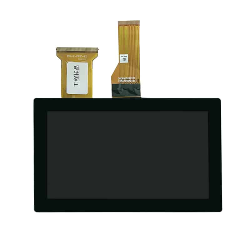
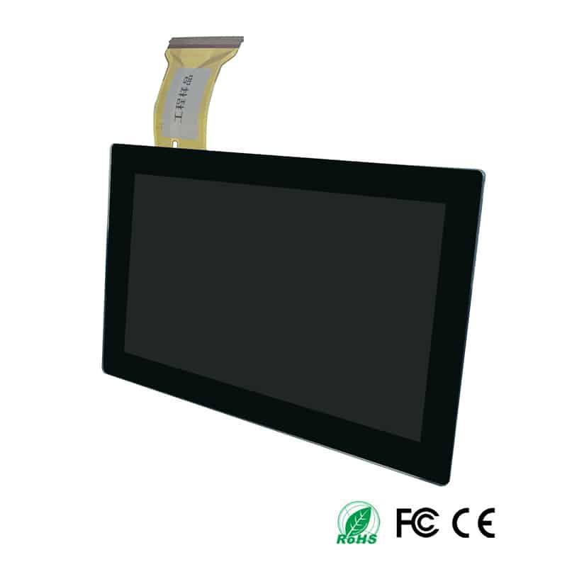
The Operator Interface PCAP Display provides a 7-inch touch interface for compact equipment that needs clear status graphics, setup menus, parameter entry and direct operator control. Its 800 × 480 resolution creates a practical landscape canvas for machine states, numeric values, alerts and touch controls without requiring a large front panel.
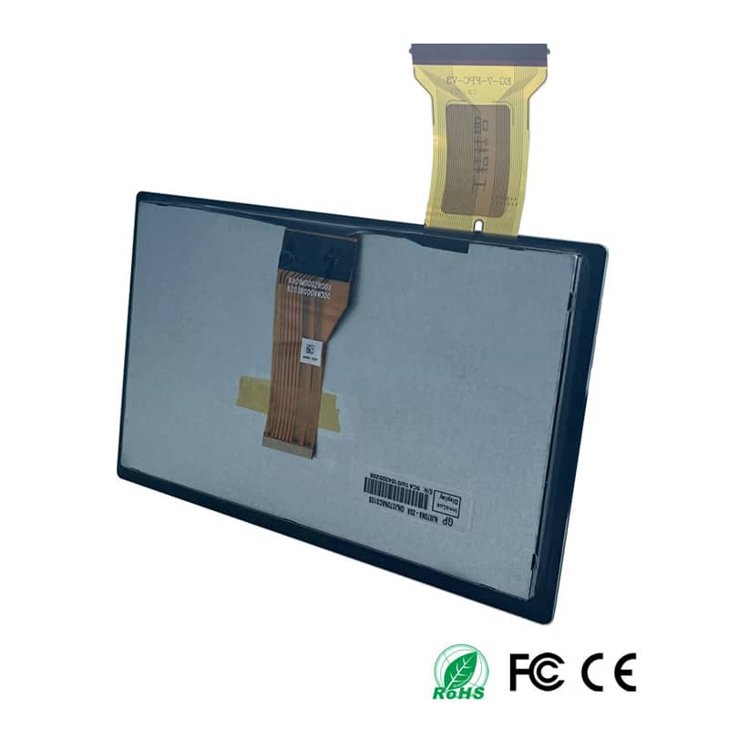
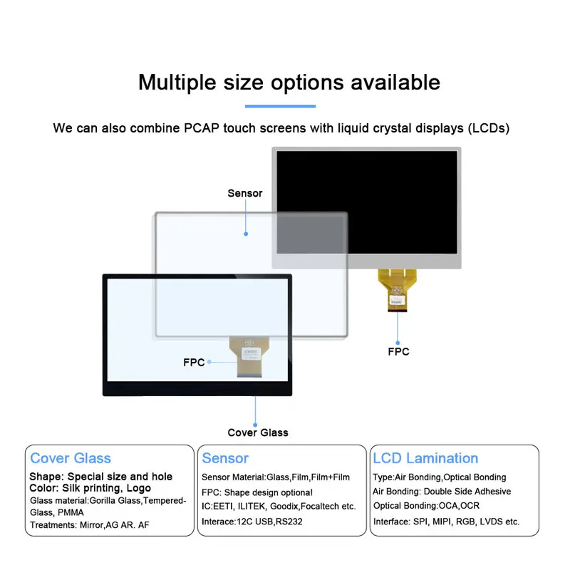
The assembly combines a TFT LCD with a G+G projected-capacitive touch panel. Display data uses a 50-pin parallel RGB interface, while touch data uses a separate 3.3 V I²C connection. USB touch can be implemented through an appropriate I²C-to-USB bridge rather than by connecting the touch FPC directly to USB.
Key Specifications
| Specification | Value |
|---|---|
| Display size | 7 inch |
| Resolution | 800 × 480 pixels |
| LCD active area | 154.08 × 85.96 mm |
| Lens viewing area | 154.88 × 86.72 mm |
| Lens outline | 165.00 × 100.00 mm |
| Total assembly thickness | 7.73 ± 0.4 mm |
| Luminance | 1000 cd/m² |
| Viewing-angle values | 70° / 70° / 50° / 70° |
| Display interface | 50-pin parallel RGB |
| Touch type | G+G projected capacitive |
| Touch points | 10 points |
| Touch controller | CYTMA568 |
| Native touch interface | I²C |
| Touch supply | 3.3 V |
| Touch transparency | ≥85% |
| Surface hardness | ≥6H |
| Operating temperature | −20°C to +70°C |
| Storage temperature | −30°C to +80°C |
800 × 480 Workspace for Compact Controls
Operator UI Layout
An 800 × 480 interface can organize the screen into a primary information zone and a dedicated control region. Suitable layouts include:
- Machine-state overview
- Numeric operating parameters
- Alarm and warning indicators
- Setup menus
- Trend summaries
- Maintenance prompts
- Touch buttons
- Status bars
- Device-selection menus
- Field-service instructions
The pixel density should be evaluated against the intended viewing distance. Text, icons and touch targets should remain large enough for reliable use during movement or while wearing standard work clothing.
Viewing-Angle Qualification
Four viewing-angle values are provided, but the evidence does not establish a reliable direction order for public prose. Mechanical orientation and the intended mounting direction should therefore be confirmed against the approved drawing and a physical sample.
The cover lens, bonding stack, front bezel and final installation angle can also affect finished viewing performance.
Operator Interface PCAP Display Integration
50-Pin RGB Display Path
The LCD uses a 50-pin parallel RGB connection. The host must generate the correct pixel data, clock and synchronization signals.
A 50-pin connector does not guarantee RGB timing, voltage or pin compatibility.
Before schematic release, confirm:
- Full pin assignment
- Connector pitch
- Contact orientation
- Logic-voltage levels
- Pixel-clock frequency
- Horizontal timing
- Vertical timing
- Data-enable behavior
- Sync polarity
- RGB data width
- Reset requirements
- LCD power rails
- Backlight voltage
- Backlight current
- Brightness-control method
- Power-up sequence
- Power-down sequence
A processor with HDMI, LVDS, MIPI or eDP output cannot drive the bare RGB panel directly unless a suitable conversion or controller board is designed into the system.
Native I²C Touch Path
The touch FPC provides a separate six-pin 3.3 V path containing:
- Interrupt
- 3.3 V supply
- I²C clock
- I²C data
- Reset
- Ground
The RGB image path and I²C touch path must be qualified separately.
Engineering should obtain the CYTMA568 implementation information needed for:
- I²C address
- Interrupt polarity
- Reset timing
- Firmware version
- Coordinate orientation
- Touch-report format
- Ten-point reporting
- Noise filtering
- Grounding requirements
- Recovery after communication interruption
Optional USB Touch Bridge
USB touch operation requires an I²C-to-USB bridge board. The demonstration setup shows the native I²C touch FPC connected to a separate conversion board, which then connects to the host through USB.
The bridge option should be treated as a separate subsystem. Confirm:
- Bridge-board model
- USB connector
- USB power requirements
- Supported operating systems
- HID implementation
- Firmware version
- Cable length
- Mounting clearance
- Electromagnetic-noise performance
- Inclusion in sample and production quotations
USB touch operation requires the specified I²C-to-USB bridge rather than a direct USB connection to the touch FPC.
Mechanical and Cover-Lens Integration
Active Area and Visible Window
The LCD active area is 154.08 × 85.96 mm. The lens viewing area is 154.88 × 86.72 mm, and the full lens outline is 165.00 × 100.00 mm.
These dimensions serve different purposes:
- Use the LCD active area to align the displayed graphics.
- Use the lens viewing area to define the visible opening.
- Use the lens outline for front-panel and adhesive geometry.
- Use the 7.73 ± 0.4 mm assembly depth for preliminary internal clearance.
The final enclosure must also account for component height, foam, adhesive, FPC bends and connector access.
FPC and Controller Clearance
The assembly contains separate flexible circuits for the LCD and touch functions. The enclosure should provide:
- Controlled FPC bend radius
- No sharp folds
- No compression under the frame
- Touch-controller component clearance
- RGB connector access
- I²C connector access
- Cable strain relief
- Protection from mounting screws
- Service-removal space
- Isolation from sharp metal edges
The display FPC and touch FPC should not be treated as interchangeable because they carry different signal groups and use separate host connections.
High-Luminance Optical Design
The LCD luminance specification is 1000 cd/m². This supports high-ambient indoor equipment, field-service tools and installations where lower-luminance displays may be difficult to read.
A 1000 cd/m² panel does not by itself prove finished-system sunlight readability.
Finished visibility depends on:
- Cover reflection
- Surface treatment
- Air gap or optical bonding
- Printed border geometry
- Display color palette
- Font weight
- Ambient-light direction
- Viewing angle
- Enclosure shadowing
- Backlight-control range
- Cover contamination
- Thermal behavior
A sample should be tested with the final cover, enclosure and user interface under representative lighting.
Touch-System Qualification
The module includes ten-point G+G projected-capacitive touch using the CYTMA568 controller. The cover has a confirmed hardness reference of at least 6H, while touch transparency is at least 85%.
Qualification should include:
- Single-touch accuracy
- Multi-touch reporting
- Drag and swipe response
- Edge-touch detection
- Small-button selection
- Coordinate rotation
- Long-press recognition
- Accidental-touch rejection
- Controller reset
- I²C recovery
- Touch after temperature exposure
- Noise immunity near switching supplies
- Grounding with the final metal frame
- Performance through the final cover stack
Glove, stylus, wet-finger and waterproof-touch performance should not be published until the selected firmware, cover configuration and assembled sample confirm those functions.
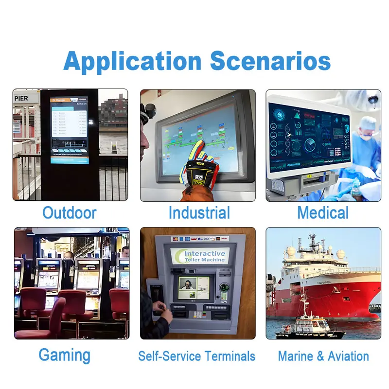
Recommended Applications
Portable Industrial Terminals
The compact 165 × 100 mm front geometry suits portable terminals that need menus, status graphics and direct touch input.
Compact Machine Controls
The screen can support setup, calibration, alarm review and operating-state selection on small machinery.
Field-Service Equipment
The 1000 cd/m² luminance and ten-point PCAP interface can support service tools used in bright workshops or changing ambient-light environments.
Test and Measurement Devices
An 800 × 480 UI can display measurement values, trend summaries, channel controls and configuration options.
Embedded Operator Panels
The module fits custom embedded equipment where the host already supports compatible parallel RGB output and I²C touch communication.
Final suitability must be established at system level. The product information does not establish IP protection, medical qualification, vehicle qualification or direct outdoor exposure capability.
Customization Scope
Engineering review may cover:
- Cover-lens outline
- Black-border printing
- Logo printing
- Touch-active area
- Touch FPC shape
- Touch FPC length
- Display FPC orientation
- CYTMA568 firmware
- I²C-to-USB bridge
- Surface treatment
- Bonding structure
- Cable assemblies
- Connector selection
- Packaging and labeling
Custom configurations are generally reviewed from 500 pieces, subject to tooling requirements, material availability and the requested specification. Sample and standard-module quantities are confirmed separately.
Procurement Checklist
Submit:
- Approved panel drawing
- Complete 50-pin RGB assignment
- Logic-voltage requirements
- Pixel-clock frequency
- Horizontal timing
- Vertical timing
- Sync polarity
- RGB data width
- LCD power rails
- Backlight voltage and current
- Brightness-control method
- Power sequence
- Host-processor details
- CYTMA568 touch specification
- I²C address
- Interrupt definition
- Reset definition
- USB bridge requirement
- Cover-lens drawing
- Visible-window drawing
- Enclosure drawing
- FPC orientation
- Connector details
- Bonding requirement
- Ambient-light target
- Operating environment
- Sample quantity
- Annual demand
- Development schedule
FAQ
About 7 Inch Operator Interface PCAP Display
What must be checked before connecting the 50-pin RGB interface?
Can the touch FPC connect directly to USB?
Is the 1000 cd/m² display sunlight readable?
Which dimensions should control enclosure design?
What does the CYTMA568 identifier confirm?
Freya Yang
+86 18318948097