Freya Yang
+86 18318948097
+852 62667476
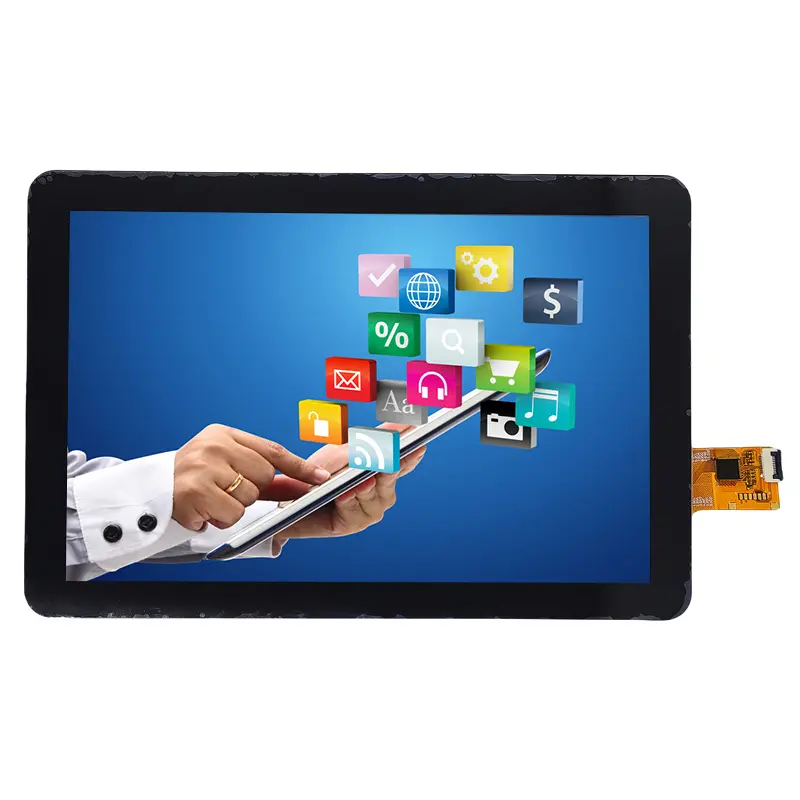
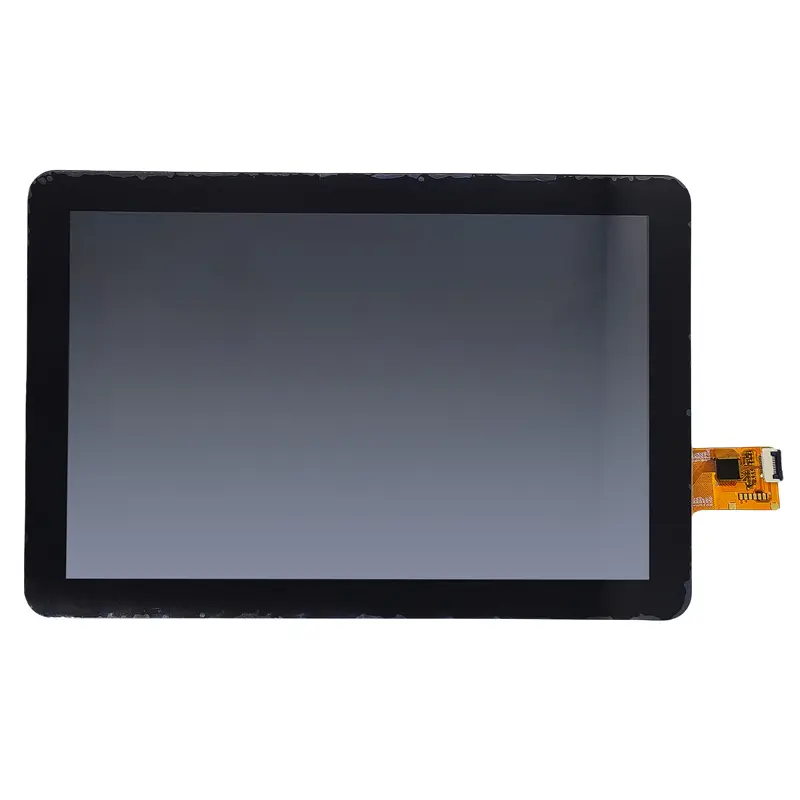
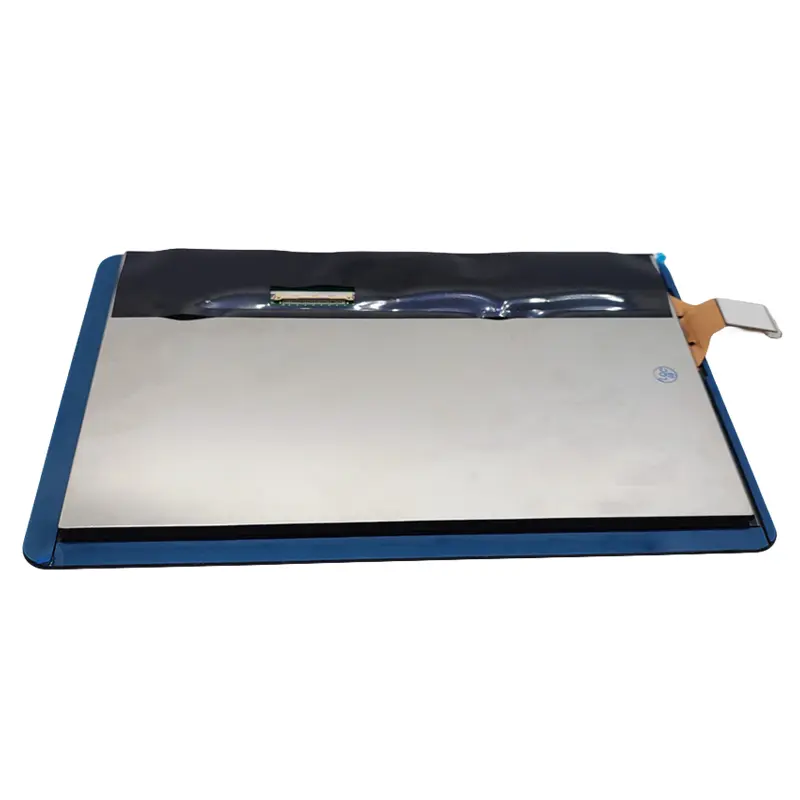
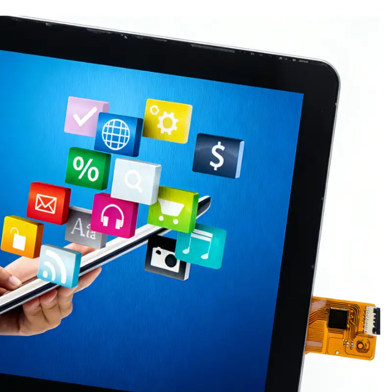
8 Inch Medical Industrial LCD Touch Screen Module for HMI
Model P/N
Size
Resolution
Brightness
Viewing Angle
Connector Type
Operating Temp
Overall(mm)
huisoar
HS080WX1-206-CTP
Brand
Panel Size (inch)
Model P/N
Resolution
Brightness (nits)
Viewing Angle
Contrast Ratio
Response Time
Overall (mm)
Active Area (mm)
Refresh Rate
Display Colors
Panel Type
Connector Type
Operating Temp
Touchscreen Type
Storage Temp
Work Mode
Pixel Format
Input Voltage (V)
Operating Environment
Designed For
8 Inch Medical Industrial LCD Touch Screen Module for HMI
This 8-inch WXGA touch module combines 700 cd/m² typical luminance, one-channel LVDS, wide-view IPS imaging and a projected-capacitive front panel for embedded HMI integration.
Product Summary
The Medical Industrial LCD Touch Screen Module provides an 8-inch 1280 × 800 display and projected-capacitive touch structure for equipment that needs a compact landscape operator interface. Its 16:10 format gives interface designers room for status data, menus, charts, alarms and touch controls without moving to a larger front panel.
The module uses a transmissive a-Si IPS TFT LCD with 700 cd/m² typical luminance, an 800:1 typical contrast ratio and 85/85/85/85° viewing angles in the listed left, right, up and down order. Display image data is carried through a one-channel 40-pin LVDS interface. The touch controller and touch communication interface must be confirmed for the ordered configuration.
Medical-equipment use requires finished-system electrical, EMC, optical, software, cleaning, risk-management and regulatory qualification. The display module itself does not establish medical-device certification or diagnostic-image performance.
Key Specifications
| Parameter | Confirmed value |
|---|---|
| Display size | 8 inches |
| Resolution | 1280 × 800 pixels |
| Aspect ratio | 16:10 |
| Display structure | a-Si IPS transmissive TFT LCD |
| Luminance | 700 cd/m² typical |
| Contrast ratio | 800:1 typical |
| Viewing angles | 85/85/85/85° left/right/up/down |
| Display colors | 16.7M colors using Hi-FRC |
| Image interface | One-channel LVDS, one pixel per clock |
| Connector | 40 pins |
| Touch configuration | Projected capacitive touch |
| Active area | 172.222 × 107.64 mm |
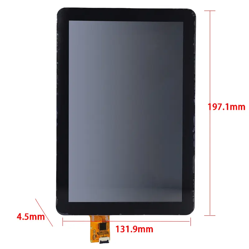
| Touch-module outline | 197.1 × 131.9 × 4.5 mm |
| Backlight | WLED; 36 white LEDs listed |
| Logic reference | 3.3 V |
| LED-backlight reference | 3.7 V |
| Operating temperature | −20°C to +70°C |
| Storage temperature | −20°C to +70°C |
700 cd/m² IPS Imaging for Operator Interfaces
WXGA Content Planning
The native 1280 × 800 raster should be used for interface design and controller validation. Native rendering preserves fine text, icons, graph lines and touch-target geometry, while the 16:10 layout provides more vertical working space than a 16:9 screen of similar width.
Engineering teams should test representative screens on the production module. Medical and industrial interfaces often need clear alarm hierarchy and readable data at varied viewing distances, so approval should extend beyond color bars or product photographs.
Viewing and Optical-Stack Review
The listed viewing range supports equipment used from different operator positions. Final visibility still depends on the front stack, installation angle, ambient light, cover-lens transmission, reflections and bonding method.
A 700 cd/m² panel can support bright indoor and protected high-ambient-light installations, but luminance alone does not establish direct-sun readability. Test the complete touch and cover structure under the intended lighting. Optical bonding may reduce internal reflections when stronger perceived contrast is required.
Color and Contrast Boundaries
The 16.7M Hi-FRC color statement and 800:1 typical contrast support standard HMI graphics and color-coded controls. They do not establish diagnostic grayscale calibration or DICOM conformance.
Integrating the Medical Industrial LCD Touch Screen Module
One-Channel 40-Pin LVDS Qualification
A matching 40-pin connector does not guarantee compatibility. Check native timing, pixel clock, one-channel LVDS mapping, bit mapping, connector orientation, logic voltage and control signals. The one-pixel-per-clock statement should be verified against the approved timing table.
HDMI, DisplayPort, MIPI or parallel RGB requires a matched controller or bridge that outputs the approved LVDS signal. Validate controller firmware and cable mapping with test patterns before releasing the motherboard or enclosure.
Separate Display and Touch Paths
The LCD image path and projected-capacitive touch path are separate functions. The touch technology is confirmed, but the controller, communication interface, connector, operating voltage, firmware and touch-point count are not established.
Obtain the touch drawing and controller specification before sample approval. Confirm whether the host requires I²C, USB or another interface, and check interrupt, reset, power, grounding and firmware requirements. Touch tuning should use the final cover lens, bonding material and enclosure ground design.
Logic and Backlight Power Planning
The electrical feature list gives 3.3 V for logic power and 3.7 V for LED-backlight power. These values refer to different functions and must not be treated as one interchangeable supply rail.
The approved electrical table must define voltage ranges, current demand, enable behavior, dimming and power sequence. The listed 36-white-LED structure also requires confirmation of its series/parallel topology and driver requirements.
Mechanical Fit for an 8 Inch Touch HMI
Active Area and Overall Stack
The active area is 172.222 × 107.64 mm, while the touch-module outline is listed as 197.1 × 131.9 × 4.5 mm. Design the enclosure around the approved visible area, touch border, connector position and tolerances rather than the nominal diagonal alone.
Review bezel overlap, FPC routing, bend radius, mounting support and service access. Confirm the 4.5 mm thickness when a custom cover lens or bonding layer is added.
Temperature Boundaries
Operating and storage ranges are listed as −20°C to +70°C. Finished equipment still needs validation for cold start, high-temperature luminance, touch response, condensation, enclosure heating and component derating.
Application Fit for Medical and Industrial Equipment
For a Medical Industrial LCD Touch Screen Module used in an operator panel, suitable projects include medical-equipment interfaces, laboratory instruments, industrial HMI panels, machine controls, portable test and service equipment, smart terminals and protected outdoor-facing controls.
Each project must qualify the display against its own safety, EMC, cleaning, environmental, optical and regulatory requirements. The module should not be described as medically certified, waterproof, sunlight readable, glove operable or universally compatible unless the ordered assembly and finished system are separately verified.
Customization and Procurement
Project review may cover the touch controller and interface, cover-lens shape and printing, optical or air bonding, AG/AR/AF treatment, brightness target, LVDS cable and controller matching, FPC definition, backlight driving, enclosure adaptation, mounting, branding and packaging.
Custom configurations are generally reviewed from 500 pieces, subject to tooling requirements, material availability and the requested specification. Samples and standard-module quantities are confirmed separately.
Procurement Checklist
Confirm:
- Native 1280 × 800 timing and one-pixel-per-clock requirement
- One-channel LVDS mapping and complete 40-pin assignment
- Connector pitch, contact side and cable orientation
- 3.3 V logic rail and allowable tolerance
- 3.7 V LED reference, current, enable and dimming requirements
- Exact 36-white-LED topology and backlight-driver design
- Touch controller, interface, voltage, pinout and firmware
- Active-area position and 197.1 × 131.9 × 4.5 mm outline
- Cover lens, bonding and optical-treatment plan
- 700 cd/m² performance behind the final front stack
- Temperature and compliance requirements
- Sample criteria, quantity and annual demand
FAQ
About 8 Inch Medical Industrial LCD Touch Screen Module
What must be checked before connecting a 40-pin LVDS controller?
Is the projected-capacitive touch interface I²C or USB?
Is 700 cd/m² sufficient behind a cover lens?
What qualification is required for medical-equipment use?
Which dimensions and power values control sample approval?
Freya Yang
+86 18318948097