Freya Yang
+86 18318948097
+852 62667476
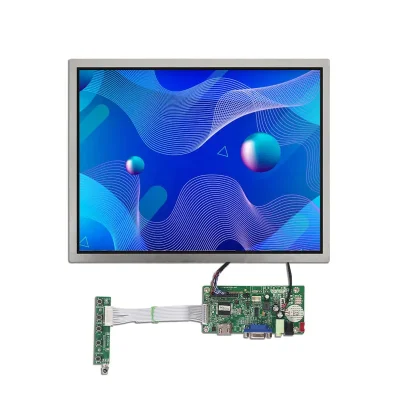
15 Inch Daylight Viewable TFT Panel for Charging Station HMIs

Model P/N
Size
Resolution
Brightness
Viewing Angle
Connector Type
Operating Temp
Overall(mm)
huisoar
HS150LW-NE10
Brand
Panel Size (inch)
Model P/N
Resolution
Brightness (nits)
Viewing Angle
Contrast Ratio
Response Time
Overall (mm)
Active Area (mm)
Refresh Rate
Display Colors
Panel Type
Connector Type
Operating Temp
Touchscreen Type
Storage Temp
Work Mode
Pixel Format
Input Voltage (V)
Control Type
Operating Environment
Designed For
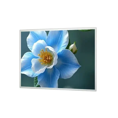
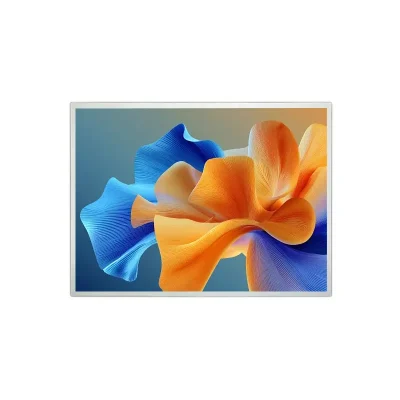
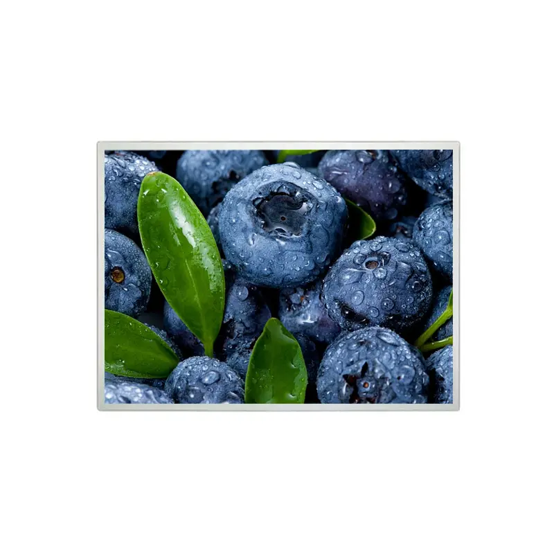
15 Inch Daylight Viewable TFT Panel for Charging Station HMIs
A 4:3 XGA panel with 1000 cd/m² typical brightness and a 20-pin LVDS connection for daylight-exposed equipment interfaces.
Product Summary
The 15 Inch Daylight Viewable TFT Panel is designed for charging-station HMIs, outdoor-facing terminals, and embedded equipment that must present clear XGA graphics under strong ambient lighting. Its 1024 × 768 resolution and 4:3 geometry support control layouts, forms, status screens, menus, and legacy graphical interfaces without requiring a widescreen software redesign.
The panel provides 1000 cd/m² typical brightness, an IPS-family viewing structure, a 20-pin LVDS connection, and a 3.3 V typical panel rail. It is supplied without an integrated touch sensor, allowing equipment manufacturers to use it as a display-only component or develop a separate touch and cover-glass assembly.
Key Specifications
| Specification | Value |
|---|---|
| Display size | 15.0 inch |
| Resolution | 1024 × 768 pixels |
| Aspect ratio | 4:3 |
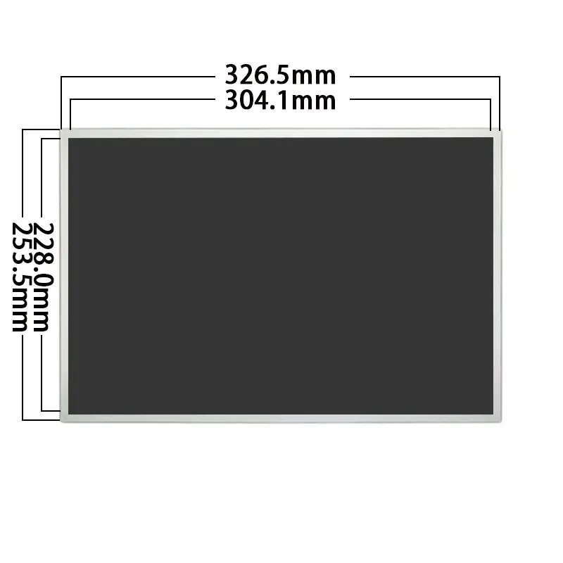
| Active area | 304.128 × 228.096 mm |
| Module outline | 326.5 × 253.5 × 10.1 mm |
| Brightness | 1000 cd/m² typical |
| Panel structure | a-Si TFT-LCD, IPS family |
| Optical mode | Transmissive |
| Contrast ratio | 700:1 typical |
| Display colors | 16.2 million colors |
| Interface | LVDS |
| Connector | 20 pins |
| Panel voltage | 3.3 V typical |
| Backlight | WLED |
| Touch panel | None |
| Operating temperature | 0°C to +60°C |
| Storage temperature | −25°C to +65°C |
4:3 XGA Layout for Equipment Interfaces
Retaining Established XGA Graphics
The native 1024 × 768 pixel format provides a familiar workspace for embedded interfaces originally designed around XGA resolution. It can support equipment menus, charging status, transaction progress, diagnostic screens, alarm lists, operating instructions, and service functions.
The 4:3 format offers more vertical space than a widescreen panel of similar diagonal size. This can benefit interfaces with stacked controls, portrait-oriented information blocks, process diagrams, or legacy software that does not scale cleanly to a 16:9 display.
A matching size and resolution do not guarantee drop-in replacement. The host timing, LVDS mapping, connector orientation, cable, supply requirements, mounting points, and module depth must also be compared.
Active Area and Enclosure Opening
The visible image area measures 304.128 × 228.096 mm. The complete panel outline is 326.5 × 253.5 × 10.1 mm.
The active area defines where the pixels are displayed, while the outline governs internal enclosure clearance. A front-window drawing should allow for the visible image, panel border, assembly tolerance, cover-glass overlap, adhesive, gasket, and any required service clearance.
The 10.1 mm panel depth does not include an added touch sensor, protective lens, optical bonding layer, controller board, cable bend, frame, or rear mounting structure.
Daylight-Viewable Optical Performance
Using the 1000 cd/m² Brightness Grade
The panel is specified at 1000 cd/m² typical brightness. This grade can improve visibility in charging equipment, kiosks, information terminals, and other installations exposed to daylight or strong interior lighting.
A 1000 cd/m² panel does not by itself guarantee readable performance in every outdoor installation. Front-glass reflectance, air gaps, touch-sensor transmission, surface treatment, viewing direction, direct-sun exposure, enclosure shading, and automatic dimming all affect the completed system.
A 1000 cd/m² panel still requires optical-stack review for daylight readability.
Engineering review should establish the target ambient-light condition, display orientation, cover-glass construction, touch requirement, reflection-control strategy, night-time dimming, backlight power, and enclosure thermal limits.
Resolving the Viewing-Angle Grade
The detailed specification lists 85°/85°/85°/85°, while a separate overview lists 89°/89°/89°/89°. Both descriptions position the product as a wide-viewing IPS-family panel, but the exact production grade should be confirmed before final optical approval.
Projects with side-mounted screens, elevated displays, short viewing distances, or multiple user positions should request the approved viewing-angle specification for the production configuration. The qualification sample should also be evaluated from the actual installation height and approach angle.
20-Pin LVDS Integration
Host Signal Qualification
The display uses a 20-pin LVDS connection. The supplied information does not establish the LVDS channel count, bit depth, bit mapping, timing table, connector series, or complete pin assignment.
Confirm:
- Native 1024 × 768 timing
- Pixel clock and blanking requirements
- LVDS channel configuration
- Color-bit mapping
- JEIDA or VESA assignment
- Connector manufacturer and pitch
- Pin-1 orientation
- Complete 20-pin assignment
- Panel-enable requirements
- Ground and shielding arrangement
- Cable length and routing
A 20-pin LVDS connector does not confirm pin mapping, voltage, or timing compatibility.
The existing panel datasheet, host schematic, controller documentation, and cable drawing should be reviewed before the panel is powered.
Panel and Backlight Power Boundaries
The identified 3.3 V typical value applies to the panel electronics. It does not define the complete backlight power requirement.
The WLED backlight may require a separate driver input, enable signal, dimming signal, current setting, and thermal limit. The project should confirm:
- Panel voltage tolerance
- Panel current
- Backlight input voltage
- Backlight power
- Enable polarity
- PWM or analog dimming
- Maximum operating brightness
- Startup and shutdown requirements
No backlight voltage, current, power sequence, or lifetime value should be assumed without the approved electrical document.
Mechanical Integration of the 15 Inch Daylight Viewable TFT Panel
Module Clearance and Mounting
The 15 Inch Daylight Viewable TFT Panel measures 326.5 × 253.5 × 10.1 mm. Mechanical review should cover mounting points, rear-component clearance, cable exit, connector access, module tolerances, front-window alignment, ventilation, and service removal.
A charging-station or kiosk enclosure may also require:
- Protective front glass
- Sealing gasket
- Metal support frame
- Optical bonding
- Brightness sensor
- Controller board
- Cable-retention feature
- Thermal path for the backlight assembly
These additions must be included in the finished depth and bezel calculation.
Adding Touch or Protective Glass
The standard panel has no touch sensor.
The standard panel has no touch sensor, so touch input requires a separately specified assembly.
A touch-enabled design should define the sensor technology, controller, host interface, cover-lens material, glass thickness, printing, bonding, FPC direction, active touch area, firmware environment, and completed stack depth.
A cover lens or touch sensor may reduce front-surface luminance and increase reflectance. Optical and brightness verification should therefore be performed on the completed assembly rather than only on the bare panel.
Environmental and Application Boundaries
The operating-temperature range is 0°C to +60°C, and the storage range is −25°C to +65°C. These limits are suitable for many commercial and protected outdoor-facing installations but do not establish operation below freezing.
The panel can be evaluated for:
- Charging station HMIs
- Outdoor-facing kiosks
- Digital signage modules
- Self-service terminals
- Public information equipment
- Access-control interfaces
- Equipment status displays
- Legacy XGA upgrades
The panel is not confirmed as waterproof, vandal-resistant, automotive-qualified, medically certified, or suitable for uncontrolled sub-zero operation. Those requirements must be addressed at the complete-equipment level.
Custom Configuration Review
Engineering review may cover:
- Cover-glass design
- Touch-sensor integration
- Optical bonding
- Reflection-control treatment
- Cable and connector details
- Backlight driving
- Dimming control
- Mechanical mounting
- Product labeling
- Qualification documentation
Custom configurations are generally reviewed from 500 pieces, subject to tooling requirements, material availability, and the requested specification. Sample and standard-module quantities are confirmed separately.
Procurement Checklist
Submit:
- Host processor or controller-board model
- Existing display model for replacement projects
- Native XGA timing
- LVDS channel and bit mapping
- Complete 20-pin assignment
- Connector and cable drawings
- Panel-voltage requirements
- Backlight power and dimming requirements
- Ambient-light conditions
- Cover-glass specification
- Optical-bonding requirement
- Touch requirement
- Enclosure and bezel drawings
- Rear-clearance limits
- Required viewing position
- Operating-temperature requirements
- Sample quantity
- Annual demand

FAQ
About 15 Inch Daylight Viewable TFT Panel
What must be checked before replacing another 15-inch XGA panel?
Is 1000 cd/m² sufficient for an outdoor charging station?
Can any 20-pin LVDS controller operate this panel?
What is required to add capacitive touch?
Freya Yang
+86 18318948097