Freya Yang
+86 18318948097
+852 62667476
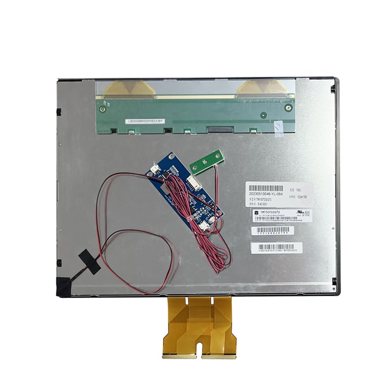
15.6 Inch USB Capacitive Touchscreen Module for Control Consoles


Model P/N
Size
Resolution
Brightness
Viewing Angle
Connector Type
Operating Temp
Overall(mm)
huisoar
HS-G156HAN02.302
Brand
Panel Size (inch)
Model P/N
Resolution
Brightness (nits)
Viewing Angle
Contrast Ratio
Response Time
Overall (mm)
Active Area (mm)
Refresh Rate
Bezel Opening
Display Colors
Panel Type
Connector Type
Operating Temp
Touchscreen Type
Storage Temp
Work Mode
Input Voltage (V)
Touch Interface
Weight (g)
Operating Environment
I/O Interface
Designed For
15.6 Inch USB Capacitive Touchscreen Module for Control Consoles
This large-format touch assembly combines 10-point USB input, an air-bonded cover structure and exact mechanical geometry for embedded control interfaces.
Product Summary
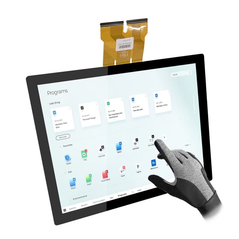
The USB Capacitive Touchscreen Module is designed for control consoles, operator terminals, embedded PCs and equipment interfaces that need a large interactive surface without relying on a finished desktop monitor.
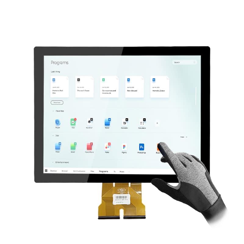
Its projected-capacitive touch system supports 10 touch points under the stated configuration. The touch controller uses a USB connection with a typical 5 V supply, while the LCD video path is handled separately. This separation allows system designers to qualify the display signal and touch communication independently.
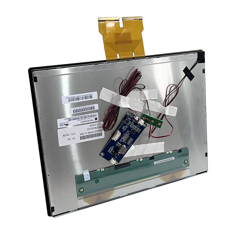
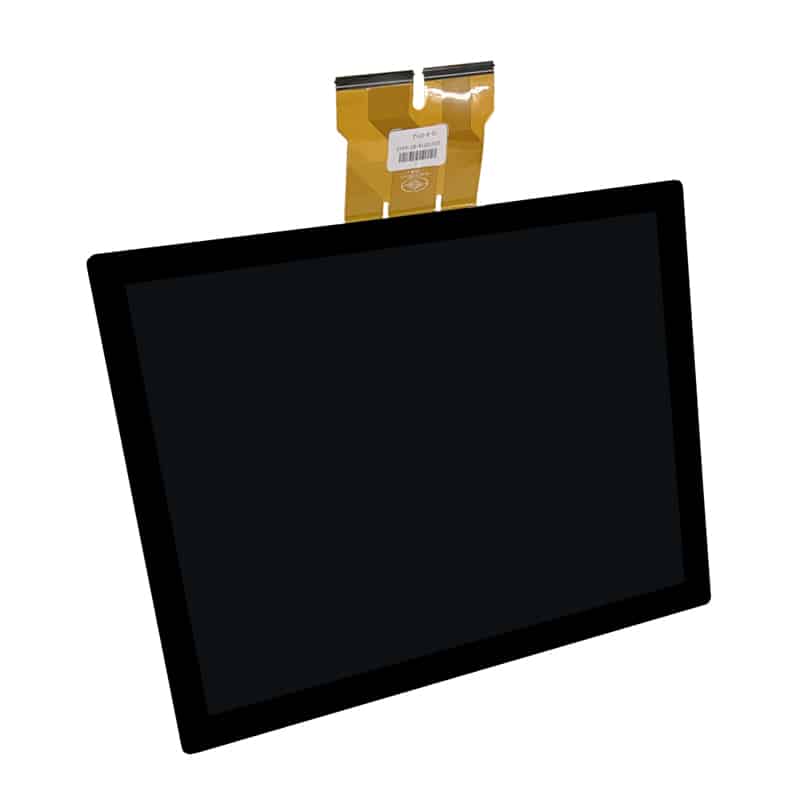
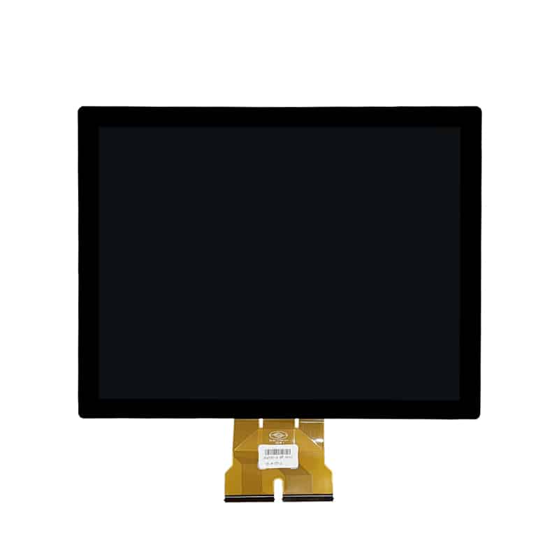
The assembly uses a 380.56 × 229.99 mm cover and an air-bonded construction with a 1 mm gap. These dimensions make enclosure, bezel and mounting review essential before tooling or sample approval.
Key Specifications
| Specification | Value |
|---|---|
| Screen size | 15.6 inch |
| Cover outline | 380.56 × 229.99 mm |
| Touch-panel view area | 344.56 × 193.99 mm |
| Touch-panel active area | 345.56 × 194.99 mm |
| Display active area | 344.16 × 193.59 mm |
| Display outline | 363.8 × 215.9 × 8.8 mm |
| Touch-panel thickness | 2.9 mm |
| Total thickness | 12.7 mm |
| Touch technology | Projected capacitive touch |
| Touch points | 10 points typical |
| Touch interface | USB typical |
| Touch-controller supply | USB 5 V typical |
| Touch report rate | ≥100 Hz |
| Touch response | ≤25 ms |
| Touch linearity | ±2 mm |
| Bonding method | Air bonding with 1 mm gap |
| Cover hardness | ≥6H |
| Impact reference | ≥IK07 |
| Touch transmittance | >85% |
| Display supply | 3.3 V typical |
| Backlight supply | 12 V typical |
| Maximum power | 12.8 W maximum |
Large-Format Touch Interface Design
10-Point Touch Interaction
The 15.6-inch surface supports interface layouts with larger controls, status panels, navigation zones and multi-window content.
Ten-point touch can support gestures and simultaneous contact tracking, but the required gesture set should be defined before firmware approval. An application that only uses single-touch buttons may need different filtering and palm-rejection behavior from an interface that uses pinch, rotate or multi-user input.
Touch validation should cover:
- Button size and spacing
- Edge-touch accuracy
- Drag and swipe behavior
- Multi-finger gestures
- Unintended palm contact
- Touch near printed borders
- Landscape and portrait orientation
- Touch calibration
- Startup and reconnection behavior
- Long-duration USB communication
Report Rate and Touch Latency
The controller is specified with a report rate of at least 100 Hz and a touch response of no more than 25 ms.
These values describe the touch path. Finished-system responsiveness also depends on USB polling, controller firmware, application processing and graphics rendering.
A fast touch controller does not compensate for delayed UI software or slow screen updates.
USB Capacitive Touchscreen Module Integration
USB Touch and LCD Video Are Separate
The USB connection carries touch data and controller power; it does not establish the LCD video connection.
The display interface is identified separately as LVDS in the product information. System designers must therefore qualify two paths:
- LCD video, power and backlight
- USB touch data and controller power
A host with a USB port still requires a compatible LCD video output or a suitable display controller.
A USB touch interface does not carry the LCD video signal.
Host and Controller Qualification
Before releasing the motherboard or cable design, confirm:
- USB connector type
- USB cable length
- Controller enumeration
- USB HID behavior
- Touch-controller firmware
- Touch-point count
- Reset and recovery behavior
- Operating-system support
- LVDS connector
- LVDS pin assignment
- LVDS channel count
- LVDS bit depth
- LCD supply voltage
- Backlight voltage
- Backlight enable and dimming
- Grounding between touch and display systems
The touch-controller brand is not confirmed by the supplied technical table and should not be inferred from marketplace wording.
Air-Bonded Display Stack
This assembly uses air bonding with a stated 1 mm gap between the touch structure and the LCD.
Air bonding is not the same as optical bonding.
The air gap can influence:
- Internal reflections
- Contrast under strong ambient light
- Parallax
- Dust-control requirements
- Condensation risk
- Mechanical stack height
- Front-surface impact transfer
- Repair and replacement methods
Projects that require reduced internal reflection or a different environmental stack should evaluate a separately approved optical-bonding configuration. Optical bonding must not be assumed for the standard assembly.
Cover Glass and Mechanical Integration
Cover and Display Geometry
The cover measures 380.56 × 229.99 mm, while the LCD outline measures 363.8 × 215.9 mm.
The touch-panel active area is 345.56 × 194.99 mm, and the display active area is 344.16 × 193.59 mm. The small difference between these areas must be considered when aligning the visible window and the touch coordinate system.
The complete stack is 12.7 mm thick, including a 2.9 mm touch structure and an 8.8 mm LCD.
Housing and Bezel Review
Before enclosure release, review:
- Cover-glass overlap
- Display centering
- Visible-window dimensions
- Printed border width
- Adhesive location
- Gasket position
- Bezel pressure
- LCD rear clearance
- FPC routing
- USB cable exit
- LVDS cable exit
- Connector retention
- Thermal expansion
- Service access
- Mounting-flatness tolerance
The ≥6H cover-hardness value and ≥IK07 impact reference apply to the specified component configuration. They do not establish an IP rating or complete enclosure qualification.
Optical and Display Configuration Boundaries
The marketplace configuration identifies 250 cd/m² luminance. This level is primarily suited to indoor or controlled-light equipment rather than direct-sun installations.
A 250 cd/m² display does not establish sunlight readability behind cover glass.
The supplied materials contain conflicting native-resolution and pixel-format information. One selector shows 1024 × 768, while the mechanical dimensions describe a 16:9 display area and other pages using the same display reference show different resolutions.
For this reason, the native LCD resolution, panel revision, pixel format, contrast ratio and color depth must be taken from the approved LCD datasheet supplied for the production sample.
A selected resolution label must be reconciled with the approved LCD drawing before controller or enclosure release.
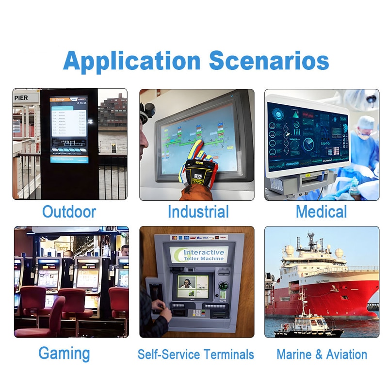
Application Scenarios
Industrial Control Consoles
The large touch area can support equipment status, alarm pages, process controls, menus and maintenance functions in indoor control environments.
Operator Terminals
The module can provide direct touch input for workstation interfaces where a separate embedded computer or industrial controller supplies the video signal.
Embedded PCs
USB touch communication can be paired with an embedded PC, provided the selected operating system and touch-controller firmware are verified.
Business Equipment Interfaces
The assembly can support conference equipment, service terminals, information interfaces and commercial control products under controlled indoor conditions.
Equipment Dashboards
The wide 16:9 cover geometry can accommodate multi-zone dashboards with status data, navigation and command controls.
These applications do not establish medical, outdoor, maritime or automotive qualification.
Customization Scope
Project-specific review can cover:
- Cover outline
- Cover thickness
- Printed border
- Logo printing
- Transparent windows
- Touch active area
- Touch-controller selection
- USB cable and connector
- Touch FPC geometry
- Surface treatment
- Air-bonding tape
- Optical-bonding alternative
- Display-panel selection
- LVDS cable definition
- Brightness target
- Front gasket design
- Mounting structure
- Enclosure integration
- Packaging
Custom configurations are generally reviewed from 500 pieces, subject to tooling requirements, material availability and the requested specification. Sample and standard-module quantities are confirmed separately.
Procurement Checklist
Submit:
- Approved LCD model and revision
- Native LCD resolution
- LCD datasheet
- LVDS pin assignment
- LVDS channel and bit-depth definition
- Display connector drawing
- LCD supply requirements
- Backlight voltage and current
- Backlight enable and dimming requirements
- USB connector requirement
- USB cable length
- Target operating system
- Touch-point requirement
- Gesture requirement
- Touch-controller preference
- Cover drawing
- Printed-border drawing
- Visible-window dimensions
- Enclosure drawing
- Mounting method
- Gasket and sealing requirement
- Air-bonding or optical-bonding requirement
- Brightness target
- Environmental target
- Sample quantity
- Annual demand
- Project schedule
FAQ
About 15.6 Inch USB Capacitive Touchscreen Module
What must be checked before connecting the touch assembly to an embedded PC?
How does air bonding differ from optical bonding in this assembly?
Which dimensions should control the enclosure design?
Can the selected 1024 × 768 option be used without further verification?
Does ≥IK07 mean the finished terminal is waterproof or vandal proof?
What is the lead time for standard TFT display modules in your inventory?
Lead time for standard TFT display modules depends on current inventory levels and order volume. For the HS-G156HAN02.302 model, please contact our sales team with your quantity requirements to receive a confirmed lead time. We typically stock popular sizes and can provide estimated schedules upon request.
What are the available connector types and pinouts for your 21.5" LVDS panels, and do you offer adapter cables or reference designs?
This 15.6" module uses an LVDS display connection. For 21.5" LVDS panels, connector types and pinouts vary by model. We recommend requesting the specific datasheet for the 21.5" panel you are interested in. Adapter cables and reference designs can often be provided based on your system requirements; please confirm with engineering.
What are the brightness levels available for industrial displays, and can you customize beyond 1500 nits?
The HS-G156HAN02.302 offers a typical brightness of 300 nits. For industrial displays requiring higher brightness, custom options may be available. If you need brightness beyond 1500 nits, please provide your target value and environmental conditions so our team can evaluate feasibility and recommend suitable solutions.
Do you offer anti-glare or anti-reflective coatings as standard or as an option on your industrial panels, and how do they affect optical performance?
The standard configuration for this module does not specify anti-glare or anti-reflective coatings. Such coatings can affect optical performance by reducing reflections but may slightly impact contrast or clarity. If you require these coatings, please discuss with our engineering team to assess compatibility and any trade-offs for your application.
Can you integrate touch controllers (resistive/capacitive) into custom display modules with specific firmware requirements?
Yes, we can integrate touch controllers with custom firmware into display modules. For this 15.6" module, the projected capacitive touch controller uses a USB interface. If you have specific firmware requirements, please share the details (e.g., gesture support, noise filtering) so we can evaluate and provide a tailored solution.
Freya Yang
+86 18318948097