Freya Yang
+86 18318948097
+852 62667476
17 Inch Legacy Control System TFT LCD Module Industrial LCD Panel for Retrofits

Model P/N
Size
Resolution
Brightness
Viewing Angle
Connector Type
Operating Temp
Overall(mm)
huisoar
HS170ETN-NE10
Brand
Panel Size (inch)
Model P/N
Resolution
Brightness (nits)
Viewing Angle
Contrast Ratio
Response Time
Overall (mm)
Active Area (mm)
Refresh Rate
Display Colors
Panel Type
Connector Type
Operating Temp
Touchscreen Type
Storage Temp
Work Mode
Control Type
Operating Environment
I/O Interface
Designed For
17 Inch Legacy Control System TFT LCD Module Industrial LCD Panel for Retrofits
Its 5:4 SXGA canvas, 1000 cd/m² luminance and 30-pin LVDS support control-system display replacement after timing and enclosure checks.
Product Summary
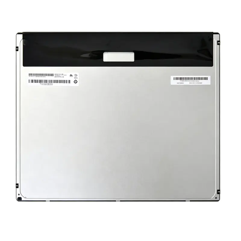
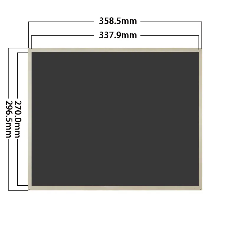
A Legacy Control System TFT LCD Module helps equipment manufacturers sustain products that were designed around a 17-inch 1280 × 1024 interface. This TN panel combines a 5:4 SXGA canvas, 1000 cd/m² typical luminance, a 30-pin LVDS connection and a 358.5 × 296.5 × 10.8 mm module envelope.
The 337.92 × 270.336 mm active area supports control screens, alarms, charts and operating menus without forcing a widescreen redesign. Its standard configuration is non-touch, with 16.7M colors, a 1000:1 typical contrast ratio and a WLED backlight.
A matching 30-pin connector does not prove LVDS timing, channel mapping, voltage or pin compatibility.
Key Specifications
| Parameter | Value |
|---|---|
| Display size | 17 inches |
| Native resolution | 1280 × 1024 pixels |
| Aspect ratio | 5:4 |
| Panel structure | a-Si TN TFT-LCD, transmissive |
| Active area | 337.92 × 270.336 mm |
| Module outline | 358.5 × 296.5 × 10.8 mm |
| Luminance | 1000 cd/m² typical |
| Contrast ratio | 1000:1 typical |
| Viewing angles | 85°/85°/80°/80°, left/right/up/down |
| Preferred view | 6 o’clock |
| Display colors | 16.7M |
| Backlight | WLED |
| Interface | 30-pin LVDS |
| Touch | No touch |
| Operating temperature | 0°C to +50°C |
| Storage temperature | −20°C to +60°C |
Why the 5:4 SXGA Format Still Matters
Preserve Native 1280 × 1024 Interface Layouts
Industrial software often remains tied to a fixed pixel canvas. Alarm windows, machine diagrams, soft keys and data tables may have been designed specifically for 1280 × 1024 output. Replacing the panel with a widescreen format can require scaling, unused borders or a complete interface redesign.
A native SXGA panel allows the existing application to retain its original geometry when the controller timing and signal mapping are compatible. Confirm the output timing, pixel clock, synchronization and LVDS format before treating the module as a replacement.
Check Enclosure and Visible-Window Continuity
The 17-inch diagonal does not establish mechanical interchangeability. Use the 337.92 × 270.336 mm active area to plan the visible opening and the 358.5 × 296.5 × 10.8 mm outline to check the internal frame, depth and mounting clearance.
Connector location, cable direction, backlight components and manufacturing tolerances must also be compared with the existing display. A correct native resolution does not compensate for an incompatible outline or cable route.
Legacy Control System TFT LCD Module Integration
Qualify the Complete 30-Pin LVDS Interface
A 30-pin connector identifies only the contact count. It does not define supply voltage, LVDS channel count, bit mapping, connector orientation, enable signals or backlight control.
Before PCB or cable release, obtain the approved pin table and compare every connection with the host controller. Confirm panel power, signal grounds, differential-pair assignment, clock pairs, mapping selection and any unused or control pins.
The native 1280 × 1024 timing should also be checked against the controller board. A board described as supporting 17-inch LVDS panels may still use a different connector orientation, voltage or data map.
Separate the Bare Panel from a Controller-Board Display
This product is a TFT-LCD component, not a finished HDMI, DVI or VGA monitor. A separate controller or processor must generate the required native LVDS signal and provide the correct panel and backlight power.
Controller-board selection should be treated as a separate engineering decision. Confirm its firmware timing, cable, brightness-control method, startup behavior and power architecture with the production panel sample.
TN Viewing and 1000 cd/m² Optical Performance
Plan Around the 6 O’Clock Preferred View
The panel uses TN technology with a confirmed 6 o’clock preferred viewing direction. Its viewing sequence is 85°/85°/80°/80° in left, right, up and down order.
Mounting orientation matters when the operator views the display from above, below or from a fixed standing position. Test the panel in the finished orientation with representative dark backgrounds, warning colors and low-contrast interface elements.
TN can be appropriate when the equipment has a predictable operator position and the existing design depends on this module format. Projects requiring consistent appearance from many off-axis positions should compare a qualified wide-view alternative before selection.
Validate Luminance Behind the Final Front
The 1000 cd/m² typical panel rating provides a stronger optical starting point than a standard indoor display. It does not by itself establish readability through every protective front or in direct sunlight.
Cover-glass transmission, internal reflections, air gaps, surface treatment, installation angle and ambient light all affect the finished display. Test the complete optical stack in the intended equipment rather than approving visibility from the panel value alone.
The 1000 cd/m² panel rating still requires front-cover and ambient-reflection testing.
Mechanical and Environmental Fit
Use the Active Area and Outline for Different Design Checks
The active area determines where useful pixels appear. The module outline controls enclosure clearance. Both dimensions are required during retrofit review.
Check the front-window opening against 337.92 × 270.336 mm and the available cavity against 358.5 × 296.5 × 10.8 mm. Include tolerance for brackets, cable bend radius, rear components and assembly access.
A replacement decision should also include connector position and the location of the active area within the outer frame. Similar overall dimensions do not guarantee that the visible image will align with the existing bezel.
Apply the Confirmed Temperature Limits
The panel is specified for operation from 0°C to +50°C and storage from −20°C to +60°C. These are component limits, not complete-equipment environmental ratings.
Measure the internal enclosure temperature near the display during maximum brightness and maximum ambient operation. Fans, sealed cabinets, processor heat and solar loading can raise the panel environment above the room temperature.
Humidity, condensation, shock and vibration grades are not confirmed and require separate system qualification where relevant.
Application Fit and Selection Boundaries
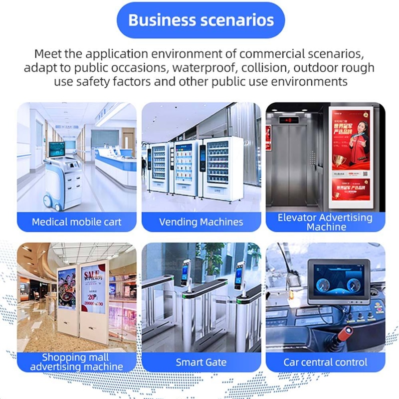
This Legacy Control System TFT LCD Module is suitable for factory-control terminals, CNC interfaces, test and measurement equipment, monitoring consoles, charging or dispenser interfaces and other 17-inch 5:4 systems after compatibility review.
The module is particularly relevant when the existing software, front opening and operator workflow depend on a native 1280 × 1024 display. It should not be represented as an automatic replacement solely because another panel is also 17 inches and uses a 30-pin connector.
The standard configuration is non-touch. Projects requiring resistive or capacitive input need a separately engineered touch stack, controller, interface and mechanical drawing.
Configuration and Customization
Project review can cover controller-board and LVDS cable matching, connector definition, cover glass, anti-glare or anti-reflective treatment, optical bonding, touch integration, brightness evaluation, enclosure adaptation, mounting and branding.
Custom configurations are generally reviewed from 500 pieces, subject to tooling requirements, material availability and the requested specification. Sample and standard-module quantities are confirmed separately.
Procurement Checklist
Confirm the following before sample or production approval:
- Approved model-specific datasheet and drawing
- Native 1280 × 1024 timing
- Pixel clock and synchronization requirements
- LVDS channel and bit mapping
- Complete 30-pin assignment
- Connector orientation and cable direction
- Panel supply voltage and current
- Backlight voltage, current, enable and dimming
- 337.92 × 270.336 mm active-area position
- 358.5 × 296.5 × 10.8 mm module fit
- Mounting tolerances and rear clearance
- 6 o’clock viewing orientation
- Final front-cover optical stack
- 1000 cd/m² lighting target
- Standard non-touch or separately engineered touch requirement
- 0°C to +50°C operating requirement
- −20°C to +60°C storage requirement
- Sample-validation criteria
- Quantity and annual demand

FAQ
About 17 Inch Legacy Control System TFT LCD Module Industrial LCD Panel
What must be checked before replacing another 17-inch 30-pin LVDS panel?
How should the existing 1280 × 1024 interface be validated?
Is 1000 cd/m² sufficient behind protective glass?
How does the 6 o’clock preferred view affect mounting?
When should this TN panel be selected instead of a wide-view alternative?
Freya Yang
+86 18318948097