Freya Yang
+86 18318948097
+852 62667476
7.84 Inch MIPI Bar Touch Display Development Kit for Smart Terminals
Model P/N
Size
Resolution
Brightness
Viewing Angle
Connector Type
Operating Temp
Overall(mm)
huisoar
HSB21-V06
Brand
Panel Size (inch)
Model P/N
Resolution
Brightness (nits)
Viewing Angle
Contrast Ratio
Response Time
Overall (mm)
Active Area (mm)
Refresh Rate
Display Colors
Panel Type
Connector Type
Operating Temp
Touchscreen Type
Storage Temp
Work Mode
Pixel Format
Input Voltage (V)
Control Type
Weight (g)
Motherboard Type
I/O Interface
Designed For
7.84 Inch MIPI Bar Touch Display Development Kit for Smart Terminals
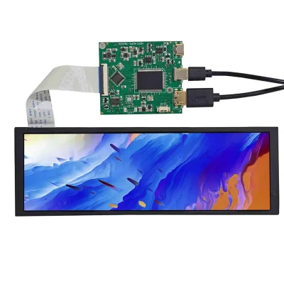
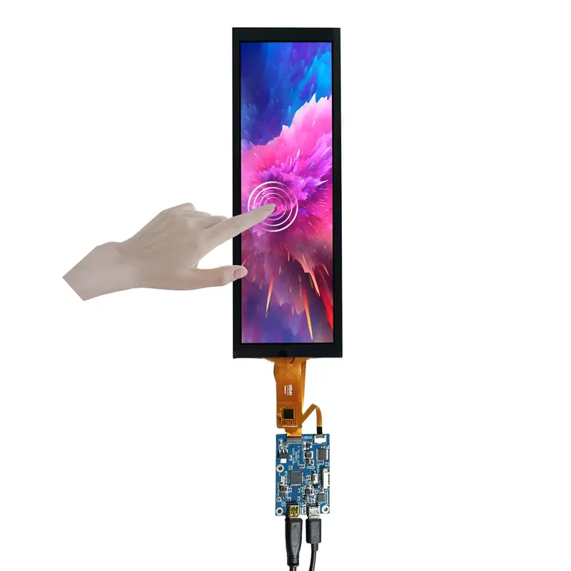
A MIPI Bar Touch Display Development Kit gives developers a compact way to evaluate a tall 400 × 1280 touch interface without starting from a bare panel alone. The 7.84-inch TFT-LCD combines a narrow portrait format, 600 cd/m² typical luminance, capacitive touch, a 40-pin MIPI FPC connection and a paired controller-board path. It fits prototypes and smart-terminal concepts where a conventional landscape screen does not suit the available front-panel geometry.
Product Summary
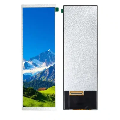
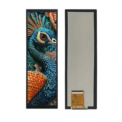
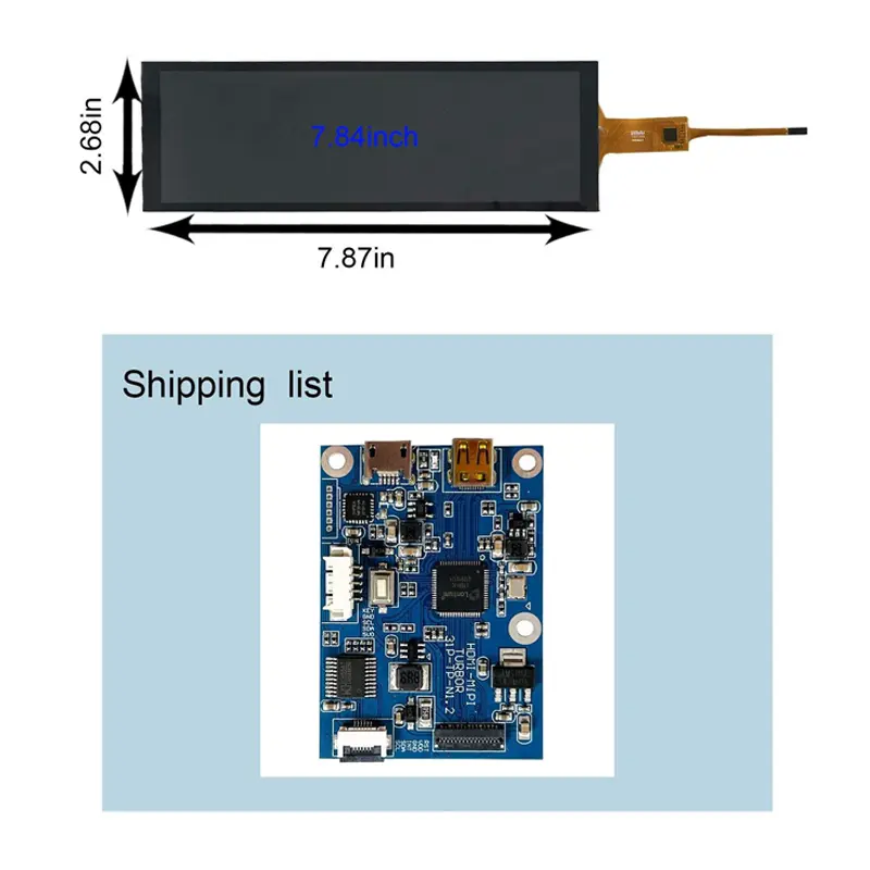
The display uses a normally black, transmissive TFT-LCD structure with an active area of 64.8 × 199.88 mm inside a 67.7 × 205.68 × 3.2 mm outline. Its 80°/80°/80°/80° typical viewing specification is defined in left/right/up/down order at CR ≥10.
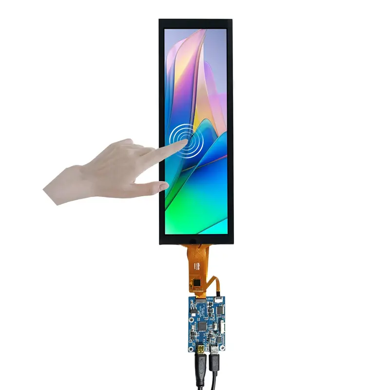
Capacitive touch is confirmed for the screen assembly. The LCD image path is identified as MIPI through a 40-pin FPC, while the exact touch controller and touch communication interface must be locked to the ordered revision before host-board release.
Key Specifications
| Specification | Value |
|---|---|
| Display size | 7.84 inches |
| Resolution | 400 × 1280 pixels |
| Display mode | Normally black, transmissive TFT-LCD |
| Brightness | 600 cd/m² typical |
| Contrast ratio | 800:1 typical |
| Viewing angle | 80° / 80° / 80° / 80° L/R/U/D at CR ≥10 |
| Active area | 64.8 × 199.88 mm |
| Screen outline | 67.7 × 205.68 × 3.2 mm |
| LCD interface | MIPI, 40-pin FPC |
| Panel voltage reference | 1.8 V / 3.3 V typical |
| Backlight | WLED |
| Touch | Capacitive |
| Controller input | 5 V DC, more than 0.5 A |
| Controller standby | <0.3 W |
| Controller-board size | 55 × 45 × 5 mm |
400 × 1280 Vertical Bar Format for Compact Interfaces
Use the native portrait canvas
The 400 × 1280 raster supports vertically stacked controls, status regions, menus and information panels. Designing the UI at native resolution avoids unnecessary scaling and makes better use of the narrow 64.8 mm active-area width.
A rotated installation can also be evaluated, but orientation should be confirmed with controller behavior, touch mapping and cable direction before enclosure release.
600 cd/m² for controlled bright environments
The 600 cd/m² typical luminance provides useful output for prototypes, smart-terminal panels and indoor equipment under stronger ambient lighting.
A 600 cd/m² panel rating does not by itself establish direct-sun or weatherproof outdoor performance.
Capacitive Touch and 40-Pin MIPI Integration
Qualify the complete MIPI connection
The LCD signal interface is a 40-pin MIPI FPC. Connector count alone is insufficient for controller qualification because lane assignment, clock and data routing, signal voltage, reset behavior, timing and pin mapping can vary.
A matching 40-pin FPC does not establish MIPI lane, timing, voltage, pin-mapping or initialization compatibility.
Confirm the complete display pinout, FPC contact orientation, controller-board revision and cable definition before hardware release.
Keep touch qualification separate
Capacitive touch is confirmed, but the current configuration does not establish the touch-controller model, touch bus, address, interrupt/reset signals or touch-point count. The MIPI connection defines the LCD image path; it should not be assumed to define touch communication without the ordered touch documentation.
Integrating the MIPI Bar Touch Display Development Kit
Separate panel and controller power
The LCD specification gives 1.8 V / 3.3 V typical input references, while the controller-board requirement is stated separately as 5 V DC with more than 0.5 A available.
The LCD voltage references and the 5 V controller input are separate electrical requirements and should not be merged without the approved schematic.
Controller standby is listed below 0.3 W, but this is not the maximum operating power of the complete assembly.
Lock the controller revision
The kit selector and packing information identify a VS-RGB21-V06 board, while another compatibility line names VS-MIPI0784-V54. Treat this as a revision-control item.
Confirm the exact board label, firmware, host-video input, screen cable and touch connection on the approved sample before production purchasing.
Mechanical Integration and FPC Clearance
Approve the screen outline before tooling
The screen outline is 67.7 × 205.68 × 3.2 mm, while the active area is 64.8 × 199.88 mm. The final mechanical drawing should also control the FPC exit, touch tail, cable bend, controller location and connector access.
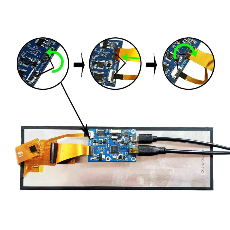
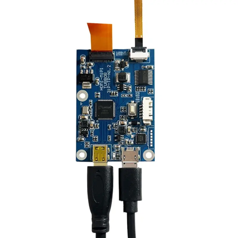
The controller board occupies approximately 55 × 45 × 5 mm, so rear clearance must include the board and attached cabling. The MIPI Bar Touch Display Development Kit should therefore be treated as a screen-plus-board integration package rather than a single mechanical component.
Smart Terminal and Prototype Application Fit
The tall geometry works for smart-terminal prototypes, compact equipment controls, developer fixtures and secondary information interfaces where horizontal width is constrained. Capacitive touch supports menu-driven interaction without relying entirely on physical buttons.
The kit is useful for evaluation because the screen and controller-board path can be tested together before a custom host board or enclosure is finalized. It should not be treated as proof of compatibility with an arbitrary MIPI host or outdoor enclosure.
Included Components and Project Options
The identified kit includes the 7.84-inch capacitive touch LCD screen, a controller board and two connection leads. Exact connector functions and board revision should be confirmed against the ordered sample.
FPC definition, controller matching, cable geometry, cover-lens design, touch tuning, optical treatment, enclosure adaptation and mounting can be reviewed by project. Custom configurations are generally reviewed from 500 pieces, subject to tooling requirements, material availability and the requested specification. Sample and standard-kit quantities are confirmed separately.
Procurement Checklist
Before approving the MIPI Bar Touch Display Development Kit, confirm native 400 × 1280 orientation, complete 40-pin MIPI assignment, lane configuration, FPC contact side, 1.8 V / 3.3 V panel requirements, touch-controller and touch-interface definition, controller revision, 5 V DC input and required current, screen and board dimensions, 600 cd/m² lighting target, sample criteria and annual demand.

FAQ
About 7.84 Inch MIPI Bar Touch Display Development Kit
What must be checked before connecting the 40-pin MIPI screen to another controller?
Which power value applies to the LCD and which applies to the controller?
Is the capacitive-touch interface carried through the same 40-pin MIPI FPC?
What should be validated for a 400 × 1280 vertical interface?
Which controller-board model should be specified for production?
Freya Yang
+86 18318948097