Freya Yang
+86 18318948097
+852 62667476
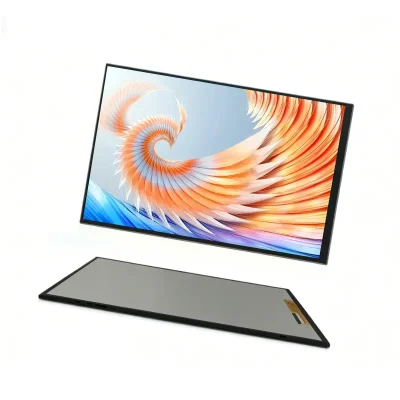
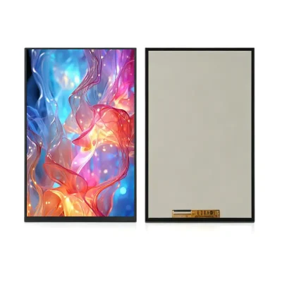
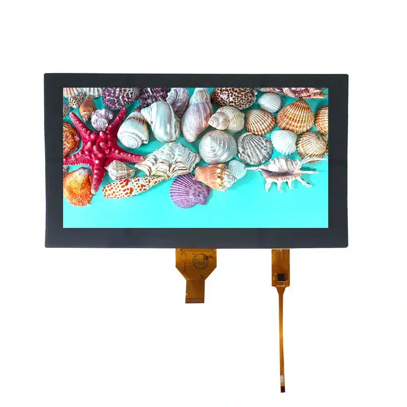
10.1 Inch WSVGA MIPI Display Module for Embedded HMI

Model P/N
Size
Resolution
Brightness
Viewing Angle
Connector Type
Operating Temp
Overall(mm)
huisoar
HS101WS05A
Brand
Panel Size (inch)
Model P/N
Resolution
Brightness (nits)
Viewing Angle
Contrast Ratio
Response Time
Overall (mm)
Active Area (mm)
Refresh Rate
Display Colors
Panel Type
Connector Type
Surface Treatment
Operating Temp
Touchscreen Type
Storage Temp
Work Mode
Control Type
Operating Environment
Motherboard Type
Designed For
10.1 Inch WSVGA MIPI Display Module for Embedded HMI
This slim landscape TFT provides native 1024×600 output through a 30-pin MIPI connection, with capacitive touch available as a project option.
The 10.1 Inch WSVGA MIPI Display Module is a landscape TFT component for embedded interfaces that need a practical balance of screen area, UI readability, and compact mechanical depth. Its native 1024×600 resolution supports control dashboards, status panels, settings pages, and graphical operating interfaces without implying the processing hardware or enclosure of a finished monitor.
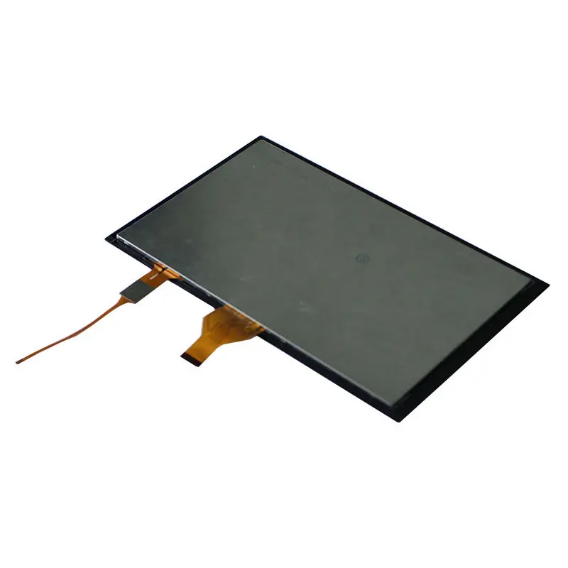
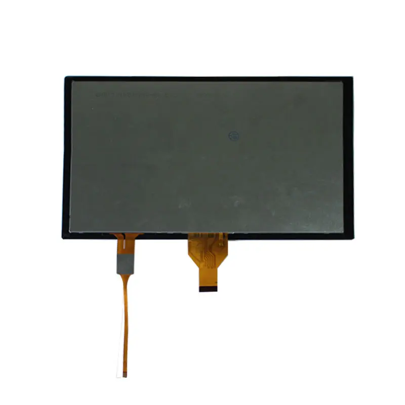
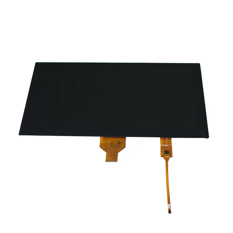
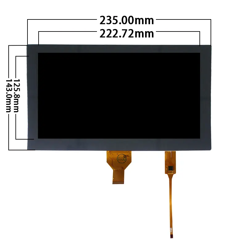
The module uses a 30-pin MIPI display connection and has a 222.72 × 125.28 mm active area within a 235.0 × 143.0 × 2.8 mm outline. Capacitive touch can be evaluated as part of the ordered assembly, but the touch controller, signal interface, lens dimensions, and firmware requirements must be confirmed for the selected configuration.
Key Specifications at a Glance
| Parameter | Value |
|---|---|
| Display size | 10.1 inch |
| Native resolution | 1024 × 600 pixels |
| Resolution class | WSVGA |
| Format | 16:9 landscape |
| Display interface | MIPI |
| Connector | 30-pin FPC |
| Active area | 222.72 × 125.28 mm |
| Module outline | 235.0 × 143.0 × 2.8 mm |
| Touch configuration | Optional capacitive touch |
| Operating temperature | −20°C to +70°C |
| Storage temperature | −30°C to +80°C |
A production host should be approved against the complete MIPI timing, lane definition, pin assignment, voltage levels, FPC orientation, and mechanical drawing rather than against resolution or connector count alone.
WSVGA Layout for Embedded Interfaces
The 1024×600 format provides a wide graphical workspace for machine controls, device setup pages, monitoring data, menus, and multimedia-oriented interfaces. Its 16:9 shape is well suited to landscape enclosures where horizontal space is available for navigation bars, charts, status blocks, and side-by-side information.
Native-resolution UI planning
A user interface designed directly for 1024×600 can avoid scaling artifacts and unnecessary graphics processing. Engineering teams should define:
- Native framebuffer resolution
- Text and icon sizes
- Touch-target dimensions
- Landscape rotation
- Safe margins around the bezel
- Boot-screen orientation
- Image scaling policy
- Controller output timing
The panel should normally be driven at its native resolution unless the approved module specification explicitly supports another timing mode.
Active display area
The active area measures 222.72 × 125.28 mm. This dimension controls the visible image region and should be distinguished from the 235.0 × 143.0 mm module outline.
The enclosure opening should be developed from the final drawing rather than from the active-area value alone. A suitable bezel must account for the inactive border, tolerances, adhesive, touch stack, and mounting support.
30-Pin MIPI Interface Qualification
MIPI DSI defines a serial link between a host processor and a display module. It is designed for high performance, low power, low electromagnetic interference, and reduced interconnect complexity, but a MIPI label does not create universal compatibility between panels and processors.
Parameters that must be confirmed
Before controller PCB release, verify:
- MIPI DSI version or supported mode
- Data-lane count
- Lane ordering
- Clock-lane assignment
- Native 1024×600 timing
- Video or command operating mode
- Pixel format and color depth
- Voltage domains
- Reset and enable signals
- Power sequencing
- Complete 30-pin assignment
- FPC pitch
- Contact side
- Cable insertion direction
- Backlight-control signals
The official MIPI specification supports configurable links and one or more data lanes, which is why a matching resolution or pin count is not enough to prove interchangeability.
A 30-pin FPC is not a universal interface
Another 30-pin MIPI panel may use a different lane count, pin order, voltage, control sequence, or FPC orientation. Incorrect mapping may prevent image output and can expose the panel or host to unsuitable electrical conditions.
Compatibility should be established from the approved pinout, timing table, electrical specification, and sample test.
Interface Conversion and Controller Selection
A native MIPI panel cannot be connected directly to every common video output.
When a bridge board is required
A bridge or controller board is required when the host provides:
- HDMI
- DisplayPort
- eDP
- LVDS
- Parallel RGB
- USB video
- Another incompatible MIPI timing or lane arrangement
The bridge must produce the module’s approved 1024×600 MIPI signal, not merely a generic 1024×600 output.
Controller-board review
Controller selection should cover:
- Source video format
- Output resolution
- MIPI lane capability
- Timing programmability
- Pixel format
- Power rails
- Reset control
- Backlight control
- Connector and FPC routing
- Startup behavior
- Thermal and EMC constraints
MIPI DSI supports embedded-display applications, but successful integration still depends on implementation-specific electrical and timing details.
Optional Capacitive Touch Integration
Capacitive touch is an available project configuration rather than a guaranteed feature of every base LCD.
LCD and touch are separate subsystems
The display data travels through the MIPI LCD connection. A capacitive-touch assembly normally requires a separate controller and control interface. The exact touch architecture must be specified before host-board and cable design.
Confirm:
- Touch-controller model
- Touch interface
- Touch connector and pinout
- Supply and logic voltage
- Interrupt signal
- Reset signal
- I²C address when applicable
- Touch-point requirement
- Coordinate orientation
- Cover-lens dimensions
- Sensor-to-display alignment
- Firmware or driver requirements
Do not assume that the 30-pin LCD FPC also carries the touch-control signals.
Touch mechanical stack
Adding capacitive touch can change:
- Total thickness
- Overall width and height
- FPC exit locations
- Bezel opening
- Optical transmission
- Surface reflection
- Mounting pressure limits
- Bonding method
- Weight
- Enclosure tolerances
The approved touch-assembly drawing should therefore control the finished front-panel design.
Mechanical Integration of the 10.1 Inch WSVGA MIPI Display Module
The LCD outline is 235.0 × 143.0 × 2.8 mm, while the active image region is 222.72 × 125.28 mm.
Slim module profile
The listed 2.8 mm depth supports compact products, but it represents the LCD configuration and should not be treated as the complete depth of a touch lens, adhesive, rear components, support frame, cable bend, or protective cover.
Mechanical planning should include:
- LCD support zones
- Rear-component clearance
- FPC bend radius
- Connector insertion space
- Touch-stack depth
- Bezel overlap
- Adhesive thickness
- Housing tolerance
- Thermal expansion
- Service access
Panel support and stress control
The enclosure should not apply concentrated pressure to the active display region. Thin TFT glass requires controlled perimeter support and sufficient space for the FPC to move without folding against a sharp edge.
The final drawing and physical sample should be approved before mold release.
Temperature and Operating Boundaries
The stated operating range is −20°C to +70°C, with storage from −30°C to +80°C.
These values define a component-level temperature window. They do not independently establish:
- Outdoor qualification
- Condensation resistance
- Waterproofing
- UV resistance
- Vibration grade
- Automotive qualification
- Medical certification
- Chemical resistance
- Finished-product lifetime
The complete device should be evaluated with the selected touch stack, backlight, controller, adhesives, enclosure, and thermal design.
Recommended Applications
The module can be evaluated for:
- Embedded HMI panels
- Equipment dashboards
- Smart-home control interfaces
- Building-control terminals
- Commercial operator interfaces
- Portable test and service equipment
- Industrial control displays
- Connected-appliance interfaces
- Compact information terminals
- Machine setup panels
- Indoor monitoring equipment
Application approval should follow host-interface, enclosure, optical, touch, temperature, and sample testing. Regulated or safety-critical equipment requires separate system-level qualification.
Customization and Project Review
Project-specific review may cover:
- LCD and touch combination
- Touch-controller selection
- Touch-interface definition
- Cover-lens dimensions
- FPC shape and length
- Pin assignment
- MIPI lane mapping
- Brightness target
- Backlight specification
- Surface treatment
- Mechanical outline
- Mounting method
- Controller or bridge board
- Cable and connector
- Packaging and documentation
Custom configurations are reviewed case by case according to engineering feasibility, tooling, materials, target specification, and production volume. Sample and standard-module quantities are confirmed separately.
Procurement and Sample Approval Checklist
Confirm the following before controller-board and enclosure release:
- Native 1024×600 timing
- MIPI lane count
- Lane and clock mapping
- Operating mode
- Pixel format
- Color-depth requirement
- Complete 30-pin assignment
- Supply and logic voltages
- Reset and enable behavior
- Power sequence
- FPC pitch
- Contact side
- Cable orientation
- Active area
- LCD outline
- Touch requirement
- Touch-controller model
- Touch interface and pinout
- Touch-lens outline
- Total touch-stack thickness
- Backlight electrical requirements
- Brightness target
- Operating environment
- Temperature range
- Bridge or controller requirement
- Sample quantity
- Annual demand
- Production schedule
FAQ
About 10.1 Inch WSVGA MIPI Display Module
What must be checked before connecting the panel to a 30-pin MIPI host?
Does another 1024×600 MIPI display provide direct replacement compatibility?
How should capacitive touch be specified for this module?
Which dimensions should control the enclosure design?
When is a controller or bridge board required?
Freya Yang
+86 18318948097