Freya Yang
+86 18318948097
+852 62667476
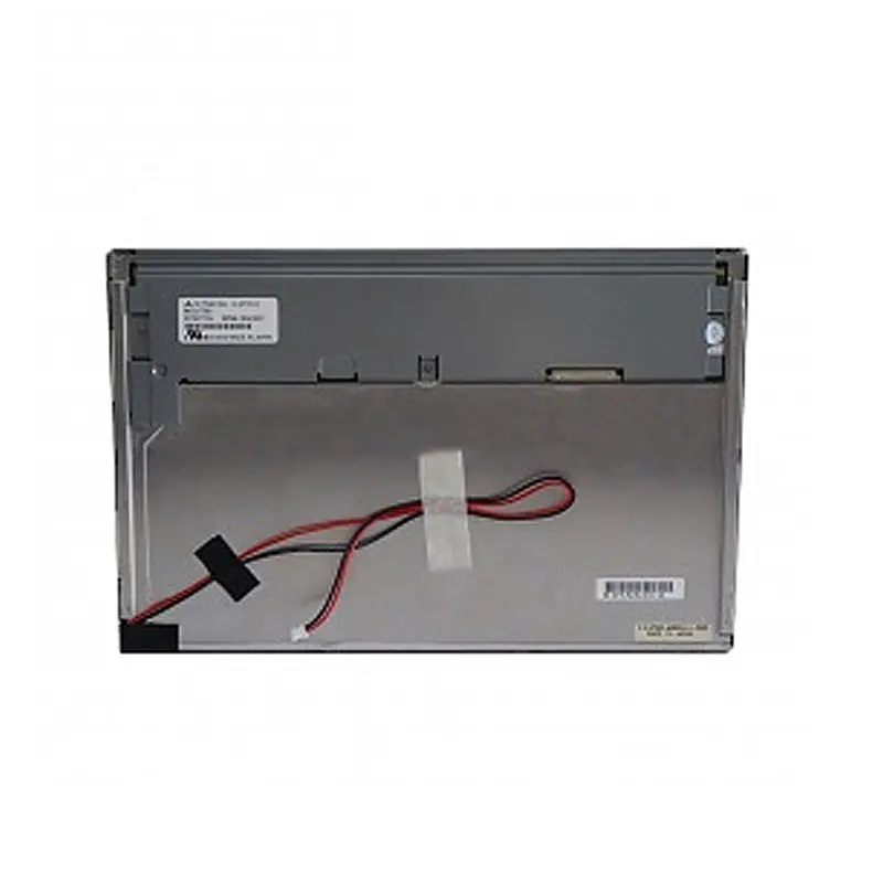
12.1 Inch Sunlight Viewable Industrial LVDS Display Module for HMI
Model P/N
Size
Resolution
Brightness
Viewing Angle
Connector Type
Operating Temp
Overall(mm)
huisoar
HS121TD-S10
Brand
Panel Size (inch)
Model P/N
Resolution
Brightness (nits)
Viewing Angle
Contrast Ratio
Response Time
Overall (mm)
Active Area (mm)
Refresh Rate
Display Colors
Panel Type
Connector Type
Operating Temp
Touchscreen Type
Storage Temp
Work Mode
Input Voltage (V)
Control Type
Operating Environment
Designed For
12.1 Inch Sunlight Viewable Industrial LVDS Display Module for HMI
A Sunlight Viewable Industrial LVDS Display Module is useful when an embedded interface needs stronger visibility in high ambient light without moving to a finished monitor architecture. This 12.1-inch module combines a native 1280 × 800 workspace, 1000 cd/m² typical luminance, a transmissive TN TFT-LCD structure and a 20-pin LVDS connection. Its standard non-touch configuration and −30°C to +80°C operating range make it relevant to industrial equipment where display integration, viewing geometry and environmental qualification are controlled at system level.
Product Summary
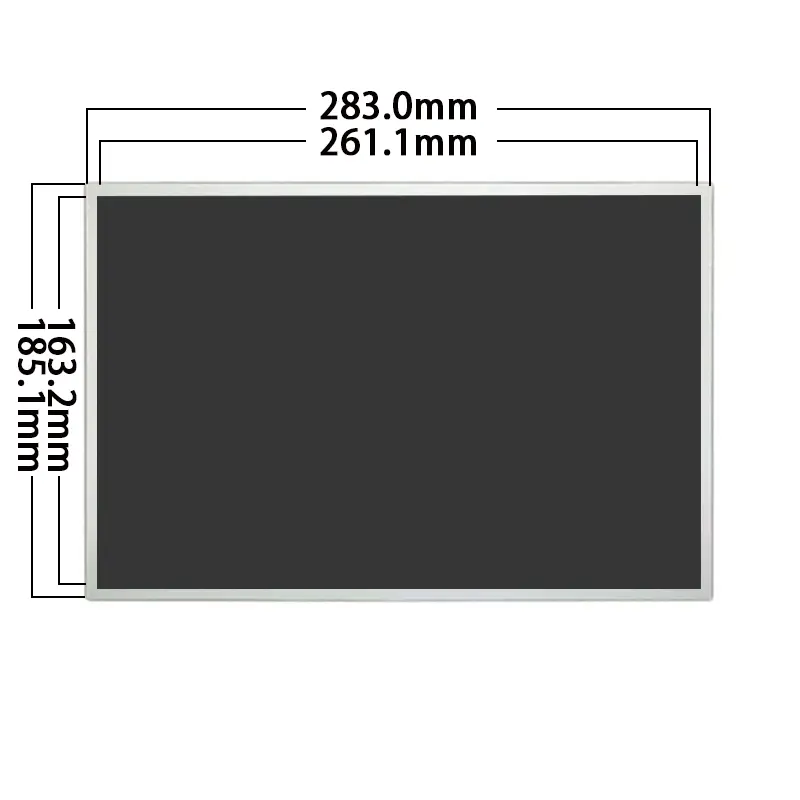
The 12.1-inch 16:10 format provides a practical workspace for machine status, operating menus, alarm information and process data. A 261.12 × 163.20 mm active area gives mechanical teams a defined visible-image region, while the module footprint is 283.0 × 185.1 mm.
The display is based on an a-Si TFT-LCD TN structure with transmissive operation. Its 1000 cd/m² typical luminance is intended for stronger ambient-light conditions than conventional indoor LCD modules, while the 700:1 typical contrast provides the specified optical baseline for UI development.
Key Specifications
| Parameter | Value |
|---|---|
| Screen size | 12.1 inches |
| Resolution | 1280 × 800 pixels |
| Aspect ratio | 16:10 |
| Active area | 261.12 × 163.20 mm |
| Module footprint | 283.0 × 185.1 mm |
| Panel technology | a-Si TFT-LCD, TN |
| Optical mode | Transmissive |
| Brightness | 1000 cd/m² typical |
| Contrast ratio | 700:1 typical |
| Preferred viewing direction | 6 o'clock |
| Display colors | 262K / 16.7M |
| Interface | LVDS |
| Connector | 20 pins |
| Panel drive voltage | 3.3 V typical |
| Backlight | WLED |
| Touch | Standard non-touch |
| Operating temperature | −30°C to +80°C |
| Storage temperature | −30°C to +80°C |
1000 cd/m² for Bright-Ambient Equipment
Brightness Is the Starting Point
A 1000 cd/m² panel provides substantially more luminance headroom for equipment installed near daylight, under strong workshop lighting or inside outdoor-adjacent enclosures. The extra output helps UI graphics and operating information compete with ambient light.
Finished-system readability still depends on more than luminance. Cover glass, reflections, air gaps, viewing angle and surface treatment can materially change the perceived contrast of a high-brightness panel. Industry optical guidance similarly treats the complete front stack—not brightness alone—as the basis for sunlight-readable performance.
A 1000 cd/m² module still requires front-window reflection and site-light testing before finished-system sunlight readability is approved.
Front-Window Qualification
For exposed or semi-outdoor equipment, engineering should define the cover material, air gap or bonding method, screen angle and expected direct-sun duration before optical release.
Anti-glare, anti-reflective treatment or optical bonding may be evaluated when reflections from the final front window reduce contrast. These treatments should be considered as part of the finished optical stack rather than assumed standard features.
20-Pin LVDS Integration
Host Timing and Pin Compatibility
The module uses a 20-pin LVDS connection. The connector count alone is not sufficient to establish replacement or controller compatibility.
Before the host board is released, confirm the native 1280 × 800 timing, LVDS channel and bit mapping, complete 20-pin assignment, connector pitch, contact side, orientation and electrical levels.
A matching 20-pin connector does not guarantee LVDS timing, voltage, mapping or pin compatibility.
An existing 20-pin cable should therefore not be reused solely because the physical connector appears to fit.
3.3 V Panel Rail and WLED Power
The specified 3.3 V typical value applies to the panel drive. It does not establish the WLED backlight voltage, current, enable method or dimming requirements.
Those backlight electrical parameters should be obtained from the approved production documentation before the LED driver or system power architecture is frozen.
The 3.3 V panel rail does not define the WLED backlight electrical requirements.
Sunlight Viewable Industrial LVDS Display Module for Fixed-View HMI
TN 6 O'Clock Viewing Geometry
The module uses TN technology and specifies a preferred 6 o'clock viewing direction. TN displays are more sensitive to viewing position than wide-view IPS architectures, so enclosure placement should be designed around the operator's expected eye position.
Display-industry guidance defines a 6 o'clock direction as a preferred viewing geometry associated with viewing from below the perpendicular center axis.
For a machine panel, pedestal terminal or cabinet interface, this can be entirely appropriate when the normal operator position is predictable.
The 6 o'clock viewing direction should be checked against the actual operator position before enclosure release.
1280 × 800 HMI Workspace
The native 1280 × 800 raster gives the module a 16:10 interface area suitable for equipment menus, status panels, graphical controls and multi-zone information layouts.
UI assets should be prepared at native resolution where practical. That avoids unnecessary scaling and allows the 261.12 × 163.20 mm active area to be used consistently when defining fonts, buttons, graphics and alarm information.
Mechanical Integration and Drawing Control
Active Area Versus Module Footprint
The 261.12 × 163.20 mm active area defines the displayed image. The 283.0 × 185.1 mm footprint controls the broader mechanical space needed inside the equipment.
Both dimensions should be considered when designing the front opening, internal support structure, bezel overlap and cable routing.
Depth Requires Production-Drawing Approval
Two thickness references are associated with the configuration: 9.7 mm maximum thickness and 10.2 mm overall depth. Tooling should not be released by selecting one value without clarification.
The approved mechanical drawing should establish the controlling module depth, tolerance, rear-component keep-out area and connector clearance.
Wide-Temperature Integration
The specified operating and storage ranges are both −30°C to +80°C. This provides a broad environmental design window for industrial equipment that may experience seasonal temperature changes or non-office operating conditions.
The panel temperature rating does not by itself establish the environmental rating of the complete machine. Enclosure temperature, solar load, ventilation, humidity, sealing, vibration and regulatory requirements remain system-level qualification items.
Applications
A Sunlight Viewable Industrial LVDS Display Module with 1000 cd/m² luminance and a fixed-view TN architecture is well suited to industrial HMIs, control cabinets, outdoor-adjacent equipment, information terminals and other embedded interfaces where the operator position is reasonably predictable.
The standard configuration is non-touch, making it particularly suitable when interaction is handled by physical controls or when the equipment developer plans to engineer a separate front-glass or touch assembly.
Customization and Procurement
LVDS cable/controller matching, complete pin definition, front glass, AR/AG treatment, optical bonding, enclosure adaptation, viewing-orientation planning and optional system-level touch development can be evaluated according to the project.
Custom configurations are generally reviewed from 500 pieces, subject to tooling requirements, material availability and the requested specification. Sample and standard-module quantities are confirmed separately.
Procurement Checklist
Before sample or production approval, confirm:
- native 1280 × 800 timing;
- complete 20-pin LVDS pin assignment;
- LVDS channel and bit mapping;
- connector pitch, contact side and orientation;
- 3.3 V panel rail and current requirement;
- WLED voltage, current, enable, dimming and driver scope;
- 261.12 × 163.20 mm active area;
- 283.0 × 185.1 mm module footprint;
- approved depth resolving 9.7 mm versus 10.2 mm;
- approved viewing-angle data;
- 6 o'clock preferred viewing direction;
- 1000 cd/m² typical luminance and tolerance;
- 700:1 typical contrast;
- 262K / 16.7M color configuration;
- standard non-touch configuration;
- −30°C to +80°C operating range;
- −30°C to +80°C storage range;
- front-window reflection target;
- environmental sealing and compliance requirements;
- sample criteria, quantity and annual demand.
FAQ
About 12.1 Inch Sunlight Viewable Industrial LVDS Display Module
What must be checked before connecting a 20-pin LVDS host?
Is 1000 cd/m² sufficient behind the final front window?
How should the 6 o'clock TN viewing direction affect enclosure placement?
Can this LVDS module connect directly to an HDMI source?
Which depth should be used for enclosure tooling?
Freya Yang
+86 18318948097