Freya Yang
+86 18318948097
+852 62667476
21.5 Inch Panel Mount LCD Module for Industrial HMIs
Model P/N
Size
Resolution
Brightness
Viewing Angle
Connector Type
Operating Temp
Overall(mm)
huisoar
HS215LVDS19201080IPS-30T
Brand
Panel Size (inch)
Model P/N
Resolution
Brightness (nits)
Viewing Angle
Contrast Ratio
Response Time
Overall (mm)
Active Area (mm)
Refresh Rate
Display Colors
Panel Type
Connector Type
Surface Treatment
Operating Temp
Touchscreen Type
Storage Temp
Work Mode
Pixel Format
Input Voltage (V)
Control Type
Weight (g)
Operating Environment
I/O Interface
Designed For
21.5 Inch Panel Mount LCD Module for Industrial HMIs
This Full HD a-Si TFT-LCD module supports panel-mounted equipment with 30-pin dual-channel LVDS, controlled-light visibility and optional touch integration.
Product Summary
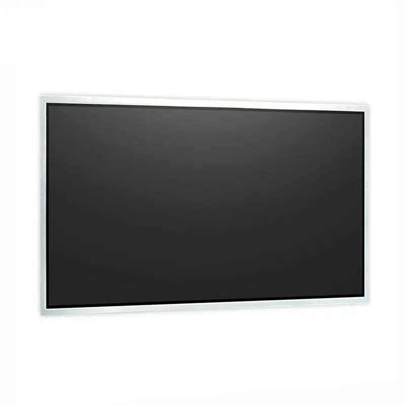
The Panel Mount LCD Module is a 21.5-inch Full HD display component for operator terminals, equipment dashboards, control panels and custom monitor assemblies. Its 1920 × 1080 resolution provides a familiar 16:9 workspace for machine status, controls, alarms, trends, diagrams and service information.
The module has a 476.64 × 268.11 mm active area within a 495.6 × 292.2 × 10.6 mm outline. Standard luminance is 300 cd/m², making it appropriate for indoor and controlled-light installations rather than direct-sun environments.
Touch can be reviewed as an optional project configuration. It should not be assumed to be included in the standard module.
Key Specifications
| Parameter | Confirmed value |
|---|---|
| Display size | 21.5 inches |
| Resolution | 1920 × 1080 pixels |
| Active area | 476.64 × 268.11 mm |
| Outline | 495.6 × 292.2 × 10.6 mm |
| Luminance | 300 cd/m² typical |
| Contrast ratio | 3000:1 typical |
| Viewing data | 89/89/89/89° typical, CR ≥ 10 |
| Response time | 18 ms typical, on/off |
| Color | 16.7 million colors, 72% NTSC |
| Surface | Anti-glare, 3H hard coating |
| Refresh rate | 60 Hz |
| Native interface | 30-pin, two-channel, 8-bit LVDS |
| Panel input | 5.0 V typical |
| Backlight | WLED, four strings |
| Touch | Optional |
| Weight | 1.67 kg typical |
| Operating temperature | 0°C to +50°C |
| Storage temperature | −20°C to +60°C |
Full HD Interface Design for Industrial Equipment
Prepare the UI at Native 1920 × 1080
The host should output the native 1920 × 1080 raster. Native operation preserves text shape, line clarity and interface geometry without introducing scaling artifacts.
A Full HD canvas gives system designers enough space for status regions, menu controls, alarm history, production data and process graphics. The final interface should be validated at the intended operator distance rather than assessed only on a desktop monitor.
Design for Operator Viewing Distance
Control-panel interfaces usually require fast recognition rather than dense media presentation. Key readings, alarm states and primary controls should remain visible from the normal operating position.
Button size, typography and spacing must also account for the final touch configuration. A non-touch display can use tighter information density, while a touch version normally needs larger interaction targets and additional edge clearance.
Optical Performance in Controlled Lighting
Treat 300 cd/m² as an Indoor Configuration
The standard panel luminance is 300 cd/m².
A 300 cd/m² panel does not establish sunlight-readable performance.
Front glass, bonding material, surface reflection and enclosure lighting can reduce the apparent brightness of the completed assembly. Validate the final optical stack under the actual factory, control-room or equipment-cabinet lighting.
Projects exposed to strong windows, outdoor light or direct sunlight require a separately approved high-luminance configuration rather than a marketing assumption.
Resolve the IPS and VA Designation
The optical-mode designation must be confirmed before final documentation or purchase release. The detailed parameters identify VA mode with normally black operation, while other product wording uses IPS terminology.
Do not use the suffix in the model name as proof of panel technology. Obtain an approved model-specific datasheet or panel label before publishing IPS, VA or replacement-compatibility claims.
LVDS Integration for the Panel Mount LCD Module
Confirm the Complete 30-Pin Definition
The native display interface is 30-pin LVDS with two-channel, 8-bit data.
A matching 30-pin connector does not establish LVDS compatibility.
The host and module must agree on native timing, pixel clock, channel mapping, bit mapping, connector orientation, signal voltage and complete pin assignment. TI’s LVDS integration guidance likewise treats display timing and panel-specific signal definition as essential integration data rather than relying on the connector name alone.
Separate Panel and Backlight Power
The panel input is listed as 5.0 V typical. This value should not be treated as a complete power specification for the display assembly.
The backlight uses four WLED strings, but its required driver voltage, current and dimming controls are not defined. Obtain the backlight electrical sheet and specify the driver separately.
Optional Touch and Controller-Board Scope
Touch Is a Separate Configuration
Optional touch does not mean that a touch sensor or controller is included.
An approved touch configuration should define:
- Resistive or projected-capacitive technology
- Touch-controller model
- USB, I²C, serial or other interface
- Cover-glass dimensions
- Bonding method
- Touch FPC direction
- Operating-system support
- Glove or wet-touch requirements
- Finished optical performance
The standard LCD and a touch-integrated assembly should be treated as separate orderable configurations.
Qualify the Controller and Backlight Board
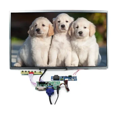
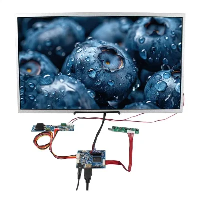
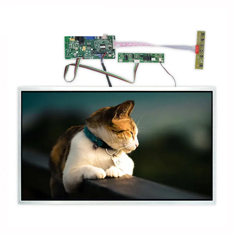
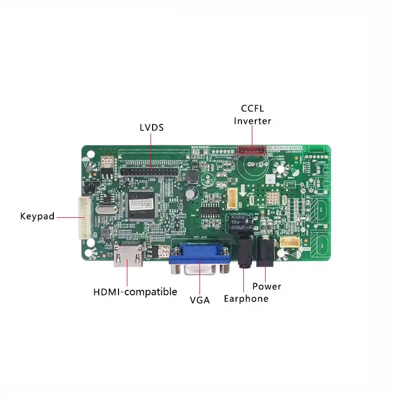
A controller board may convert HDMI-compatible or VGA signals to the module’s native LVDS input, but its inclusion and compatibility must be confirmed separately.
The pictured board also labels a CCFL-inverter connection, while the display parameters specify a four-string WLED backlight.
A CCFL-inverter output must not be connected to a WLED backlight unless a matched electrical design explicitly supports the panel.
Specify the video inputs, LVDS mapping, keypad, audio, power input, WLED driver and cables as separate system requirements.
Mechanical Panel-Mount Integration
Use Active Area and Outline Correctly
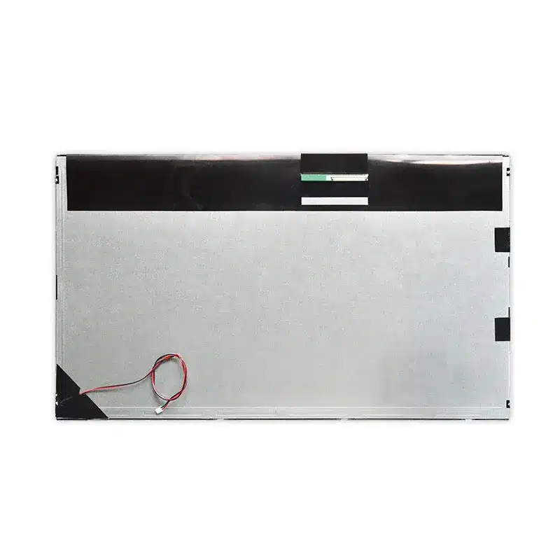
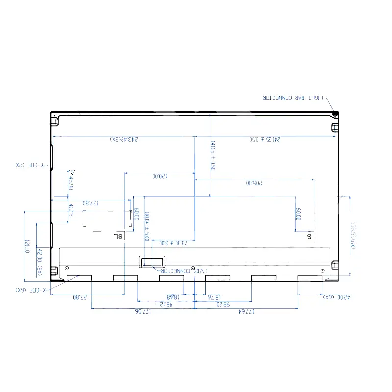
The active image area is 476.64 × 268.11 mm. The complete module outline is 495.6 × 292.2 × 10.6 mm.
The visible opening should be designed around the active area plus the approved border allowance. The enclosure must provide clearance for the panel edges, connector, LVDS cable and backlight wiring.
Define Mounting Support and Cable Clearance
The panel weighs 1.67 kg typically. The mounting structure should distribute support without twisting the display frame or applying concentrated pressure to the glass.
Include the following in the mechanical review:
- Panel-opening dimensions
- Bezel overlap
- Support points
- Fastener locations
- Cable bend radius
- Connector access
- Touch-stack thickness
- Service-removal path
- Front-cover tolerance
- Ventilation and thermal clearance
Application Fit
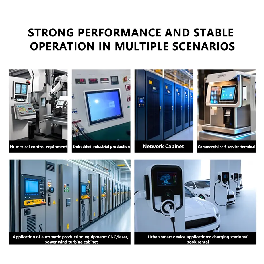
The Panel Mount LCD Module is suitable for industrial HMI panels, operator stations, machine-information displays, equipment dashboards, control-room terminals and custom indoor monitor assemblies.
The 21.5-inch Full HD format works well when the interface needs more workspace than a compact embedded display but must remain manageable within a cabinet or operator-panel structure.
The standard 300 cd/m² configuration is not intended to establish outdoor, sunlight-readable, automotive, medical, waterproof or hazardous-location suitability.
Configuration Options
Project review can cover:
- LVDS cable and host matching
- Native Full HD timing
- External HDMI-compatible or VGA controller
- WLED backlight driver
- Optional touch technology
- Touch controller and interface
- Cover glass
- Anti-glare or anti-reflective treatment
- Optical bonding
- Front bezel
- Panel-mount frame
- Enclosure adaptation
- Branding and packaging
Logo, packaging and graphic customization are identified from 2,000 pieces.
Technical custom configurations are generally reviewed from 500 pieces, subject to tooling requirements, material availability and the requested specification. Sample and standard-module quantities are confirmed separately.
Procurement Checklist
Confirm these items before sample approval:
- Whether the suffix model is distinct from the existing equivalent module
- Approved product and panel labels
- Confirmed VA or IPS designation
- Native 1920 × 1080 timing
- 60 Hz requirement
- Pixel clock
- Two-channel 8-bit LVDS mapping
- Complete 30-pin assignment
- Connector orientation and contact side
- 5.0 V panel rail
- WLED four-string voltage and current
- Dimming or PWM method
- Controller-board requirement
- HDMI-compatible or VGA input requirement
- Audio and keypad requirement
- 476.64 × 268.11 mm active opening
- 495.6 × 292.2 × 10.6 mm enclosure fit
- Panel-mount support
- Cover-glass reflection and transmittance
- 300 cd/m² lighting target
- Standard non-touch or approved touch version
- Touch technology and interface
- Operating and storage temperatures
- Sample criteria
- Quantity and annual demand
FAQ
About 21.5 Inch Panel Mount LCD Module
What must be checked before connecting a 30-pin LVDS host?
Is 300 cd/m² sufficient behind a protective front panel?
What does optional touch mean for the ordered product?
How should the IPS and VA conflict be resolved?
Can the pictured controller board and CCFL inverter be used with this module?
Freya Yang
+86 18318948097